Canned Cycle in CNC

Most CNC turning machines in precision machining factory are furnished with canned cycles equipped for performing unpleasant turning/exhausting and complete the process of; turning/exhausting. The G71 canned cycle takes various roughing passes on the workpiece while keeping a steady profundity of cut. Harsh/complete the process of turning is written in a fraction of the squares of code that it would take to compose without the canned cycle.

OD Turning Canned Cycle

Before starting the canned cycle for an external distance across turning operation the apparatus is situated at a beginning point. Toward the finish of the canned cycle the instrument will re-visitation of this equivalent point. This position is usually near the corner of where the face and the stock OD meet with clearance in both the X-and Z-tomahawks. This initial placing shows to the machine where the beginning stock measurement is and where the canned cycle will start eliminating material. The device of precision cnc machining china will naturally re-visitation of this moment that the cycle is finished. The roughing passes will begin at the external measurement and work internal until the harsh mold is finished.

Each pass will start by gradually venturing internal in the X-pivot bearing and afterward cut straight in the Z-negative course. After the heft of the material has been taken out, the cycle will make a last harsh shaping pass while leaving a completion allowance. This last pass smooths out any means gave up from different passes.
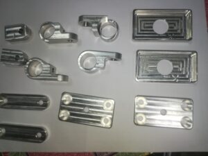
dav

Numerous Fanuc controls require two sequential G71 blocks for the roughing cycle while Has require just one. These squares regularly use factors, for example, u, R, P, Q, w, and F. For a Fanuc, a portion of similar characters utilized for factors on the main square are rehashed on the second with a different meaning, so be cautious when programming.

The primary G71 block for a Fanuc may utilize the accompanying:

. U sets the profundity of cut for each roughing pass (spiral worth).

. R sets the distance the device will withdraw from each roughing pass prior to taking a fast action to the start of the following pass.

The second G71 block for a Fanuc may utilize the accompanying:

. P indicates the grouping number where the code for the form starts.

. Q determines the grouping number where the code for the form closes.

. U sets the measure of material to be left on all distances across for later finishing.

. w sets the measure of material to be left on all countenances for later wrapping up.

. F sets the roughing feed rate. The essential Has G71 block contains the following:

. P specifies the arrangement number where the code for the shape starts.

. Q specifies the grouping number where the code for the shape closes.

. D sets the profundity of cut for each roughing pass.

.U sets the measure of material to be left on all breadths for later wrapping up.

. W sets the measure of material to be left on all appearances for later finishing.

. F sets the roughing feed rate.

The table underneath shows the configurations utilized on numerous Fanuc and Haas machines. This article is from http://www.tinymachining.com/
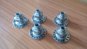
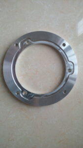
Canned Cycle Machining Process

Drilling. reaming, counter boring, and sub-setting tasks can be modified utilizing drilling canned cycles. The G74 drill cycle is frequently utilized on Fanuc turning machines and allows a peck augmentation to interrupt chip stream, forestalling long, tacky chips. The arrangement generally requires two G74 blocks. The peck augmentation is indicated with a Q-esteem. A Q-estimation of 0.25 would make the instrument withdraw once for each 0.25 of in-feed.

A few machines don’t permit a decimal in the Q-esteem and follow a 4-place design. For this situation the 0.25 would be entered as Q2500. A R-esteem determines the sum the device will withdraw after each peck. The all out supreme Z-profundity is customized as a negative an incentive in the G74 block. The customized Z-profundity should represent the length of the drill tip. Programming to accomplish a 5/16″ measurement opening that is 1.125″ profound.

On the off chance that commotion in a solitary pass without any pecks, a canned cycle is regularly not utilized, yet it is conceivable to utilize the G74 cycle if the Q-esteem is set equivalent to the full Z-profundity. With all drill cycles, the drill ought to be positioned toward the beginning area of the opening with freedom in the Z-direction when the cycle is imitated The drill will automatically re-visitation of that position toward the finish of the cycle china 4 axis cnc machining service suppliers shows a Fanuc program for performing a G74 holemaking cycle with pecks.

Boring Canned Cycles for Haas

Haas offers three different drilling canned cycles for turning machines: a G81 for a solitary pass (no peck), a G82 for single pass with a stay, and a G83 for peck drilling with a full withdraw. The complete total Z-profundity is customized as a negative an incentive for all cycle. At the point when an instrument should cut cleanly at the lower part of an opening, the G82 cycle is utilized. This cycle delays the device toward the end Z position when a P.value (number of milliseconds is indicated.

When utilizing a G83, the peck addition is determined with a Q-esteem. A Q-estimation of 0.25″ would make the apparatus completely withdraw once for each 0.25* of in-feed. A R-esteem determines the position the device will re-visitation of toward the finish of the cycle. Pecision cnc machining service factory shows a Haas program playing out a drilling cycle with a solitary pass (no pecks).

cnc precision machining company shows a Haas program playing out a drilling cycle with pecks. The table beneath shows the organizations for each drilling cycle referenced.

Tapping Canned Cycles

Understand that a tap is stiffening During tapping, the machine tomahawks just position the tap and follow along as the tap is pulled in to the work. As a tap starts cutting, the shaft turn and the feed should be accurately synchronized with the goal that the tap doesn’t tie and break under strain. A CNC machine has no sensitivity and can’t feel resistance or front when tapping. As the tap moves toward its end position, the machine should decelerate axle speed and feed proportionately with the goal that both stop promptly when the tap arrives at the last profundity. Fill the tap should converse to withdraw from the opening. Since the tap is fully occupied with the work, the shaft speed and feed should proportionately quicken to withdraw the tap from the opening without breaking.

A tap propels into the work one string for every unrest (for single lead strings). Accordingly, the feed rate per insurgency is equivalent to the essence of the tap.

This article is from http://www.tinymachining.com

Rapid Traverse

Fast navigate developments should be performed cautiously in a CNC going machine to forestall crashes. Uncommon consideration should be paid to the shifting lengths of the cutting apparatuses and that they are so near other machine parts and the workpiece. Another thought is the area of the device before and toward the fruition of the fast developments. For example, if the instrument is an ID working apparatus, be certain it is withdrawn from the ID of the part preceding making a quick movement in the X-pivot or moving to a device change position. As an instrument moves toward the work, likewise be certain that there is a lot of leeway to forestall an impact. The cutting apparatus ought to never contact the workpiece during a quick navigate development.

Direct interjection synchronizes the movement of (at least one) tomahawks to move the instrument in an orderly fashion. For china precision machining parts suppliers to create a straight line, the machine should begin moving every hub at exactly a similar time, move them at the proper feed rate, and quit moving the two tomahawks at the objective simultaneously.

To move the apparatus in a direct way on a turning place, a G1 is told alongside the directions for the end position of the development. A feed rate should likewise go with the recently customized position. Machine feed rates are communicated in the G1 block with a F-character followed by a feed esteem. A feed rate order is modular and in the event that one isn’t customized in a square, at that point the last modified rate stays dynamic.

Feed rates for CNC turning can be in either inches every moment (IPM) or inches per upset (IPR). IPR is more normal for turning. A modular G-code should be modified to set the machine control to the proposed units. On numerous machines a G98 is utilized for IPM and G99 is utilized for IPR. It is a decent practice to incorporate the ideal setting for the feed rate units toward the start of the program in the protected beginning square. cnc machining turning parts manufacturers shows an illustration of a basic direct movement between two focuses and the comparing program code.

Roundabout Interpolation for Turning- – G2 and G3

CNC turning focuses can likewise make round movements (called bends) with the device tip for machining fillets and radi. To program a curve, the instrument should initially be situated toward the beginning point where that circular segment starts. Once there, a G-code is given to demonstrate whether the curve heading is clockwise or counterclockwise. On the off chance that the curve turns clockwise from begin to end, a G2 code is utilized. On the off chance that the bend turns counterclockwise, a G3 is utilized. On most turning habitats the cutting device is on the rear of the workpiece and a G2 will make a sunken range and a G3 will make a raised sweep (corner round).

cnc precision machining factory shows a marked illustration of the significant pieces of a circular segment. It is imperative to get comfortable with every one of these parts prior to programming. Preceding cutting the bend, the cutting instrument should be situated at the curve’s beginning stage with a standard G1 or GO. After the device is in position, the code for the curve course is given and the software engineer should recognize the end point where the bend stops (recollect that the instrument is now starting toward the beginning point). Data about the circular segment’s size should be given in a similar square of code. There are two strategies for programming the size of the circular segment: programming a span esteem and recognizing the bend’s middle point area.

This article is from http://www.tinymachining.com/

CNC Control

In the present requesting and quick moving machining atmosphere, modernized mathematical control (CNC) machines are upsetting the substance of machining. These cutting edge machines can perform things that might have never been envisioned even 10 years prior. Complex tasks can be performed quicker, with more exactness and consistency, thus eagerly that it seems easy.

In a cutting edge electronic machine shop, the most ordinarily performed tasks are processing and turning. The machines playing out these tasks are essentially mechanized forms of manual processing machines and manual machines. With these two kinds of machines, most shops can create an incredible assortment of parts in all shapes, sizes, and materials. China large lathe machining parts suppliers shows instances of certain workpieces delivered by CNC machines.

The expansion of a programmed device transformer (ATC) in mix with a mechanized methods for stacking/dumping material and parts permits these machines to be run for all intents and purposes unattended. At the point when a CNC machine is furnished with a programmed apparatus transformer it is known as a turning community. A CNC plant with an ATC is known as a machining focus. Custom cnc machinery precision steel parts factory shows a CNC machine and china 3 aixs cnc machine high precision cnc machining metal parts manufacturers shows a CNC turning focus. Figure 8.1.4 shows a CNC processing machine, and medical precision machined components factory shows a CNC machining focus.

If it has an ATC, adding a CNC control to a machine empowers it to perform complex activities easily, effectively, and precisely. Only 30 years back, a portion of the activities these machines perform would have either been unimaginable or would have required various arrangements, bulky machine connections, and dreary handwork.

THE CNC MACHINE CONTROL UNIT

It requires a planned exertion between the CNC software engineer, arrangement individual, administrator, and the machine’s equipment for fruitful CNC machining to happen. A CNC program is made and put away in the machine control unit, or MCU (some of the time basically called a “control”). At the point when the program is run, this data is shipped off various frameworks on the machine that control the tomahawks movement, shaft engine, ATC, coolant siphon, and then some.

The MCU has an outer administrator control board with a presentation screen. From this administrator board and show, projects can be entered in, the machine arrangement information can be entered, and machine capacities can be observed and controlled.

CNC MOTION CONTROL

A CNC machine in activity  of tight tolerance precision machining factory can be an object of interest. By taking a customized order the machine can precisely situate its tomahawks straightforwardly at an area rapidly, precisely, and easily. The equipment that gets this going has been advancing throughout the last 25 years and consistently advances today. There are a couple of varieties of the kinds of frameworks that are utilized. The parts utilized in the most widely recognized movement control frameworks are talked about straightaway.

Most present day CNC machines utilize a cutting edge modernized adaptation of ways called straight aides. These units are fixed, have pressurized grease frameworks, and contain low-contact metal rollers. Straight aides are regularly accessible in coordinated sets, which are removable and replaceable in the field, in contrast to plain ways. high precision machining efficiency shows a cross segment of a straight slide gathering. This article is from http://www.tinymachining.com