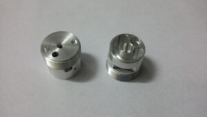
Drilling in CNC Processing Service

Canned Cycles

A few activities require redundant movements, for example, penetrating a few openings to a similar profundity or making numerous chip-breaking pecks needed for profound opening boring. Since the past boring model took three squares of movement code, 30 squares of code would be expected to penetrate 10 openings. In the event that peck penetrating is wanted, each peck needs at any rate a G1 feed move and a GO withdraw move. To help developers, CNC controls by china precision machining manufacturers have highlights that make these drawn-out and dull tasks simpler and quicker to program. These schedules can be bundled or “canned” into a couple of squares of code and are called canned cycles. Canned cycles just require a couple of squares of code in a predefined configuration to characterize the data required for the cycle. The most widely recognized canned cycles utilized on a processing machine are for boring and tapping.

Single-Pass Drilling Cycles

Single-pass penetrating cycles feed the instrument constantly to the modified Z-profundity without pecking. The cycle at that point naturally withdraws the apparatus from the opening. The two distinctive single-pass cycles for CNC processing are G81 and G82 to get china precision machine parts. The lone distinction between the two is that the G82 cycle has the ability of stopping once the full profundity is reached. This interruption is known as an abide and permits time for the apparatus to make a couple of complete unrest at the opening base, so a spotless and level surface is delivered.

Something else, the code is indistinguishable for both canned cycles. G81 and G82 function admirably for spot boring, focus boring, sub-setting, counter boring, and shallow-opening drilling.

After either canned cycle is finished, it should be dropped with a G80 code in a different square.

Single-Pass Drilling-G81

The opening drilling activity from the last model can be composed utilizing a G81 canned cycle. The area of the opening was X3.5, Y2.25 and the modified Z-profundity was 0.56. The G81 block contains the X-and Y-arrange for the opening, a return point (or R-esteem), the Z-profundity, and the feed rate. The return point is the outright Z-position where the apparatus will start taking care of and where it will withdraw to toward the finish of the canned cycle. For most circumstances, the return point ought to be equivalent to the Z-leeway plane. The table beneath shows the arrangement for the G81 cycle.

This may not appear to be an incredible reserve funds of time for one opening, yet when different openings are required, arrange areas are essentially recorded in ensuing squares after the G81 line. The canned cycle will be rehashed at each distinguished area. The instrument will withdraw to the return point (R esteem) between every area. After the last opening is penetrated, the G80 code is then used to drop the canned cycle. Assume that more openings are added to the past part, as demonstrated with high precision machining parts factory.

This article is from http://www.tinymachining.com/
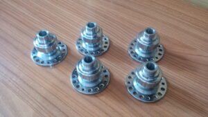
Klarm Machining, good choice for your CNC Program

M-codes are additionally used to turn coolant on and off in the machine. Coolant is typically turned on when the device rapids to the freedom plane and is normally killed toward the finish of a machining activity in china precision cnc titanium machining before an instrument change. The accompanying three coolant orders are normal:

M7 Mist coolant on

M8 Flood coolant on

M9 C oolant off

Not all machines will have the decision of fog or flood. They may just have one, so select the appropriate code for the given machine coolant framework type.

Numerous machines don’t permit a coolant code and a shaft code to be told together, since two M-codes are typically not permitted on a similar square.

A few machines get around this by permitting a M13 or a M114 code to both beginning the axle and turn the coolant on. This code doesn’t pick among flood and fog and will for the most part turn on the machine’s default coolant framework. Once more, check the machine’s manual to figure out which codes apply. In the event that a machine doesn’t acknowledge M13/M14, a different M7 or M8 order is typically customized in the square previously or after the shaft start. The coolant/shaft blend codes are:

M13 Spindle on clockwise with coolant

M14 Spindle on counterclockwise with coolant

Succession Numbers

Grouping numbers can be put toward the start of squares of code to fill in as a mark. They can be utilized for each square or irregularly all through the program to fill in as markers that help discover explicit segments of the program. Each arrangement number starts with an “N” character and they should increment through the program (e.g.. N2, N4, N6, N8, and so on; N5, N10, N15, N20; and so forth) The augmentations between numbers don’t make any difference on most machines as long as they are in expanding request. Numerous developers like to leave mathematical holes (N5, N10, N15, N20, and so on rather than N1, N2, N3, N4, and so on) so extra squares might be embedded if the program is altered later. Succession numbers are discretionary on most present day machines for standard tasks yet might be needed for certain high level activities. The program models in this unit wo exclude grouping numbers.

Finishing a Program in the Correct Format

After the program has been appropriately begun, various sorts of machining activities can be utilized to eliminate material from the workpiece. After all the material evacuation activities are done, the program will require a closure . That finishing initially withdraws the slicing apparatus to the leeway plane and turns off the coolant. Then, the shaft is paused and all machine tomahawks are moved to the machine home situations as when playing out an instrument change.

At that point one last square is required that contains just a M30 code. The M30 order closes the program and resets the program to its start. The program finishing squares may resemble this:

GO Z.1 (CLEAR PART IN Z);

M9 (COOLANT OFF);

G91 G28 Z0. M5 (RAPID TO MACHINE Z-HOME

Furthermore, SPINDLE OFF);

G91 G28 X0. YO. (Quick TO MACHINE XY-HOME);

M30 (END PROGRAM);

cnc machining metal parts suppliers china shows an illustration of a total program design for most Fanuc or Haas processing machines. This incorporates the program start data and program finishing data. Machining activities for material evacuation will be customized in the middle of the beginning and end and these tasks will be clarified all through the remainder of the unit. Survey china cnc stainless steel turning service manufacturers to see where all the data talked about so far finds a way into the CNC program.

This article is from http://www.tinymachining.com/
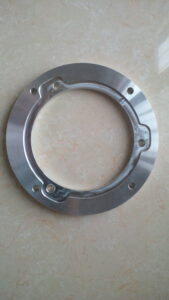
Klarm Machining, cnc milling parts components factory

Most machines switch into modular G91 (gradual situating) mode naturally during the apparatus change cycle or during the re-visitation of home position. In the event that outright situating is wanted in the program, a G90 code is required after a device change and before any further pivot developments. This square will typically incorporate a G0 (fast) and a X-and Y-hub development as demonstrated in the featured code underneath:

G91 G28 Z0. (Quick TO MACHINE Z-HOME FOR TOOL CHANGE);

G91 G28 X0. YO. (Quick TO MACHINE XY-HOME FOR TOOL CHANGE);

M1(OPTIONAL STOP);

M6 ____ (CHANGE TOOL);

G54 (SET WCS 1);

GO G90X_ Y_ (RAPID TO FIRST POSITION);

Apparatus Height Offset Command

During machine setup, the length of each apparatus is estimated and gone into the control. This is done so the machine knows where the instrument tip is thus that the apparatus can be modified from its tip paying little heed to its length. This estimation is known as the apparatus stature counterbalance (or instrument length balance). This interaction of setting an apparatus stature counterbalance will be clarified in detail by china tooling cnc machining suppliers, yet when programming, it is critical to comprehend the code required so the machine utilizes the right instrument tallness balance.

dav

After a particular apparatus has been stacked in the machine shaft and the X-and Y-tomahawks are situated at an ideal area, another fast move is frequently modified to carry the tip of the instrument to the leeway plane. Alongside the Z-hub position for the freedom plane, this square of code should likewise contain an order for appropriate apparatus stature balance. A G43 code initiates apparatus tallness counterbalance pay in the machine control, and a H-word calls up the right balanced number (featured underneath).

G91 G28 Z0. (Fast TO MACHINE Z-HOME FOR TOOL CHANGE);

G91 G28 X0. YO. (Fast TO MAC HINE XY-HOME FOR TOOL CHANGE);

M1(OPTIONAL STOP);

M6 ____ (CHANGE TOOL);

G54 (SET WCS 1);

G0 G90X_ Y_ (RAPID TO FIRST POSITION);

G43 H1 Z.1 (ACTIVATE TOOL HEIGHT OFFSET-MOVE TO CLEARANCE PLANE);

Shaft Speed for Milling of high precision high speed fine milling machine manufacturers china

Shaft speeds for CNC processing in cnc milling services suppliers are communicated in RPM and customized with the mix of a M-and S-order. The request for the M-code and the S-code doesn’t make any difference on most machines for china used cnc milling machine. The S-order gives the shaft RPM and the accompanying M-orders are utilized to kill the axle on or:

M3 Spindle on clockwise (forward)

M4 Spindle on counterclockwise (invert)

M5 Spindle off

For instance, M3 S2000 implies clockwise shaft pivot at 2000 RPM, and M4 S500 implies counterclockwise axle revolution at 500 RPM. A M5 will stop the axle. In the event that the axle is turning, another S-code can be called at any spot in the program, and the speed will be refreshed.

The axle start and speed codes might be added to the square that contains the transition to the Z leeway plane and enacts the apparatus stature balance as high-lit underneath:

G91 G28 Z0. (Quick TO MACHINE Z-HOME FOR TOOL CHANGE);

G91 G28 X0. YO. (Quick TO MACHINE XY-HOME FOR TOOL CHANGE);

M1(OPTIONAL STOP);

M6 T____ (CHANGE TOOL);

This article is from http://www.tinymachining.com/
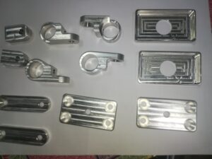
Klarm Machining Promotes CNC Milling Machining

Custom Fixtures

At the point when a section has an exceptional shape and needs exact area alongside a profoundly secure clasping framework, a custom installation can be utilized. An installation is a specially fabricated workholding gadget explicitly intended to oblige a particular part. This technique can be extremely valuable for protecting parts with abnormal shapes and permits reliable referring to from basic dimensional surfaces.

Installations are normally costly because of their absolutely custom nature, which requires a lot arranging, plan, custom machining, and numerous materials. Custom installations are generally braced straightforwardly to a machine table, bed, or gravestone. China precision machining services suppliers shows a custom apparatus.

Cycle PLANNING

Normal CNC processing activities incorporate face and fringe processing, opening, taking, two-dimensional shaping, three-dimensional surfacing, and holemaking. Every one of these individual undertakings is alluded to as an activity. The mix of all tasks needed to machine a section is known as an assembling interaction.

Before programming or setting up apparatuses and the machine, the designing drawing should be firmly analyzed and the creation of the part should be arranged beginning to end. The arranging of workholding gadgets, tooling, and the request for machining activities rely upon the part’s highlights, resiliences, and required surface completions determined by the drawing. When an intensive system has been resolved to deliver a section, the means are then definite on an archive called a cycle plan. This arrangement will incorporate a portrayal of every activity, the apparatuses required, speed and feed information, workholding data, different notes and remarks, and frequently a sketch portraying the part direction. This report is significant not just for the underlying programming of the part, yet additionally as a kind of perspective for any arrangement individual or administrator who will machine the part later on.

There is no normalized design for composing a CNC program that is viable with all machine control brands and models. Each machine control producer has built up its own interesting programming design.

Every one has minor contrasts, yet the standards of a program are something very similar among them all. The programming models all through this unit will relate the most near Fanuc-type and Haas regulators. Be that as it may, the standards might be applied to any producer’s organization (see each machine’s modifying manual).

Recollect from the CNC presentation unit that G90 sets supreme situating and G20 sets inch units. Presently the G17 has been added to set the XY plane, or the standard arrange framework direction. All programming models in this unit will be in outright mode and on the XY plane.

This article is from http://www.tinymachining.com

Klarm Machining Offers precision machining services china

CNC shell-plant and face-factory holders are basic arbors utilized for mounting shell factories and face factories. The arbor comprises of a round pilot distance across for precisely finding the focal point of the mounted instrument and two contradicting drive keys to forestall rotational slippage on the arbor. Cutters slip over the pilot and the drive keys with no power and the instrument is caught and attached by a fastener or cap screw. CNC machining products manufacturers china shows a face-plant toolholder for use in a CNC machining focus.

CNC Tapping Toolholders

There are a few varieties of CNC toolholders utilized for mounting taps. Some hold taps unbendingly in the holder. Others hold taps in particular spring-stacked gadgets that permit expansion and pressure. These are regularly called coasting holders. The machine’s ability for tapping figures out which kind of holder ought to be utilized by cnc precision machining company.

Taps can be held unbendingly with collet throws utilizing ER tap collets fabricated with an inward square that keeps the tap from turning inside the collet. Another technique for tap holding utilizes a spring-stacked brisk change connector to hold the tap. The connector would then be able to be mounted in an uncommonly planned gliding or inflexible tapping throw.

Workholding

CNC hardware and tooling are incredibly costly speculations, so it is reasonable that the additional time a machine spends really machining the item, the more productive the venture is. Workholding gadgets and strategies for machining focuses are consistently advancing and improving so that less time is invested stacking workpieces and more energy is spent machining.

Workholding gadgets for processing can go from basic clips and machine tight clamps to detailed and costly bed frameworks, headstones, and custom apparatuses.

Clips

Clips are a general strategy for connecting workpieces to a machine’s table. Similar styles utilized for manual processing can be utilized for CNC processing also. One kind of clasping framework is the progression block style that permits a stud or jolt to be moored to the machine table T-space and a lash to be drawn down onto a section’s surface to tie down it to the table. Toe cinches permit a section to be hung on its edges by utilizing exceptional serrated jaws to hold into the material and pull the work down close against the table.

Another variety is switch type cinches, which have a helpful snappy delivery switch that utilizes a cam activity component to give clipping pressure. China precision tooling manufacturer shows instances of these clip types.

Clasps are ideal for holding very huge or strangely molded workpieces, or creation work where a tight clamp isn’t reasonable and the volume of work doesn’t legitimize the cost of specially assembled apparatuses. Shockingly, holding work with braces gives no precise strategy to continued situating from one section to another. Each recently stacked workpiece may should be adjusted utilizing a dial pointer, at that point a reference area set utilizing an edge locater. Braces additionally require uncommon programming and administrator consideration since they as a rule reach out over the highest point of the workpiece surface, making the potential for crashes high. Figure 8.5.21 shows an enormous workpiece got to the table of a machining focus with step clasps.

This article is from http://www.tinymachining.com

Turning Tool Usage in CNC Machining

X apparatus balance is being set by igniting of an OD of 1.500″ with a 0.010″- thick sensor gage. The nonexistent diametral position the instrument is at is the workpiece width in addition to twice the sensor gage: 1.500 + 0.010 + 0.010 = 1.520. In the event that an ID exhausting, stringing, or cutting instrument is to be set, an unbending shim is utilized as a sensor to discover the OD surface of the workpiece as appeared (the shim isn’t utilized in the figuring).

When cnc turning manufacturer setting a turning device for the X-hub, the instrument tip is brought to the work width and ignited the OD of the part utilizing a piece of shim material or a sensor gage. At the point when an OD apparatus is ignited with a sensor gage against an external breadth, the device tip is at a fanciful width of the OD in addition to multiple times the antenna gage thickness. For instance, if the apparatus is ignited of an OD of 1.500″ with a 0.010″- thick antenna gage, the nonexistent measurement the device is at is the workpiece breadth in addition to twice the sensor gage: 1.500 + 0.010 + 0.010= 1.520. Numerous controls permit this number to be gone into the math counterbalance page and will ascertain the instrument balance sum consequently.

When china cnc turning and milling suppliers setting a math balance for an opening working device, the device might be adjusted on focus most precisely by “clearing” around the perimeter of the device with a pointer mounted in the machine shaft.

A cnc turning precision titanium parts factory shows a picture of an opening working device being cleared with an axle mounted pointer. When the opening working device is in arrangement, the device is at X-zero and there isn’t anything extra to make up for. The position is entered as the X calculation balance esteem. The Z-pivot counterbalance for opening working devices is set and changed a similar path likewise with turning and exhausting instruments.

The underlying settings of the device counterbalances are put away in the calculation balance page. Figure 8.4.19 shows a picture of an ordinary math balance page on the machine show screen. These numbers mirror the genuine setting for the device tip area in its unique and unworn state.

After the instrument has been set, a section is typically delivered by running the program interestingly. The part is then quickly reviewed and changes are made to the calculation balances on a case by case basis to accomplish wanted sizes. Here is a theoretical illustration of how these changes might be made for a turning apparatus (OD working):

  1. The initial segment is created and assessed.
  2. The estimation uncovers that every width (which is made by the X-pivot) for a given apparatus estimates 0.0008″ bigger than wanted size.
  3. The math balance page is opened and the current X-hub calculation balance for the device is 8.7899″.
  4. Then, 0.0008″ is deducted from the complete X-hub apparatus counterbalance an incentive for that instrument and it is resolved that 8.7891″ is the right calculation balance.
  5. The new worth is entered for that counterbalance.
  6. The following part is made and the revision is checked.

CNC Precision Machining Company Setting a Work

The workpiece arrangement technique builds up a work counterbalance or beginning area for the WCS. AIll workpiece arranges for programming will be referred to from this beginning. This is set up by finding the work counterbalance or “move” from the MCS starting point to the proposed WCS birthplace.

Review that the MCS never changes position. It is referred to at a similar position each time the machine is homed. Consider this point a perpetual reference point. Since the situation of this machine starting point never shows signs of change, yet the work cause changes with each new workpiece arrangement, the work balance for the part is characterized as a distance referred to from the MCS root. A few controls consider this counterbalance a workshift in light of the fact that it basically moves the machine inception to the area of the work beginning (or the other way around relying upon the machine). Carbon fiber cnc service factory shows an illustration portraying work counterbalance.

On turning machines, the workpiece will change long and position from one occupation to another and requires the cause to be reset in the Z-pivot for each new position. Notwithstanding, the middle line of the workpiece and the middle line of the axle hub are constantly adjusted, so the cause for the X-pivot stays as before from one occupation to another.

There are numerous varieties in the manner every maker’s machine is set up. The standards in the models portrayed next ought to apply to all machine controls.

Fundamental strides for setting a work balance:

  • The workpiece is introduced in the machine.
  • The turret is ordered to a confronting apparatus by utilizing the device change order.
  • The Z-hub is run to bring the confronting instrument close to the furthest limit of the workpiece.
  • The axle is begun utilizing the legitimate M3 or M4 code in MDI mode.
  • The part is looked by running a confronting device across the work utilizing the handwheel until the face is tidied up (no surface left un-machined).
  • The turret is run to a protected position and filed to a vacant position.
  • A gage block is held against the essence of the part.
  • The face of the turret is gradually and painstakingly ran against the gage block until a slight drag is felt. The length of the square is the separation from the planned part beginning to the essence of the turret (the reference point).
  • This gage block length is deducted from the current MCS Z-pivot position.
  • The coming about esteem addresses the separation from the MCS beginning to the WCS source for the Z-hub and is gone into the work balance page in the MCU.

The china cnc machining process supplier shows an illustration portraying the part, gage square, and turret being utilized to set a work balance.

It is a common misinterpretation that the drawtube string commitment affects cinching pressure. The drawtube just sets the size range among open and shut position. Eventually, the grasping pressing factor is resolved exclusively by the machine’s air or pressure driven controller for the collet/hurl nearer framework.

Some turning MCUs such as precision stainless steel cnc turned parts manufacturers utilize a less complex technique, and as opposed to deciding a genuine distance, they simply require a “set Z” catch to be squeezed. The MCU consequently plays out the computation and stores the right an incentive on the work counterbalance page.

Set Up the Workingholding in CNC Machining

When the workholding gadget is picked, it is mounted by the maker’s rules. When utilizing a hurl, machinable delicate jaws are frequently utilized in china professional cnc machining center. Delicate jaws can be redone to oblige the state of the workpiece. Frequently, the jaws are exhausted while introduced on the hurl to build up the right grasping sweep where the jaw contacts the part. It is a decent practice to exhaust the jaws while they are preloaded by clipping on a piece of scrap or a hurling ring.

This mimics the anxieties the toss will be under when the real workpiece is held. The bracing strain to be utilized for grasping the work ought to likewise be set a similar when exhausting the jaws. A carbon fibre cnc cutting factory shows an image of suitably exhausted delicate toss jaws and a mating workpiece.

In the case of utilizing a collet, place the collet closer catch in the vacant position. The collet should be lined up with its key and embedded into a perfect shaft nose tighten. String the drawtube onto the collet from the opposite finish of the headstock. Spot a workpiece of the right breadth into the collet and hand-fix the drawtube until the part is held cozily. Release the drawtube a half-transform prior to securing it set up to set up the appropriate leeway for stacking and dumping workpieces. In the event that the draw tube is left cozy with the collet closer in the”open” position, workpieces won’t handily slide all through the collet during part changes (the collet can’t deliver enough).

Regardless of whether a collet or a throw is utilized, the suitable clasping pressure should be set. A lot grasping pressing factor can misshape the workpiece and too small clipping pressing factor can permit the work to slip or be pulled out of the collet or throw during machining. Too little pressing factor will likewise permit the holding power to be overwhelmed by radial power at high RPM. The china CNC machining parts manufacturers show the impacts of holding pressure versus RPM on one producer’s machines. The pressing factor of the collet/toss nearer framework is controlled either by a pneumatic or water powered controller, contingent upon the machine. The holding pressure is changed with this controller. (Allude to the machine manual for explicit strategy.)

When the workholding gadget has been set, the workpiece to be utilized for arrangement may now be held. It is critical to permit sufficient workpiece length to stretch out of the toss or collet so that there is no impact with the throw jaws or the collet face during any of the modified machining activities. Ordinarily, 1/8 ” of least leeway ought to be kept up between the cutting instrument and the workholding gadget.

It is a typical misconception for high precision machining parts factory that the draw tube string commitment affects bracing pressing factor. The draw tube just sets the size range among open and shut position. Eventually, the grasping pressing factor is resolved simply by the machine’s air or water driven controller for the collet/toss nearer framework.

This article is from http://www.tinymachining.com/
Canned Cycle in CNC

Most CNC turning machines in precision machining factory are furnished with canned cycles equipped for performing unpleasant turning/exhausting and complete the process of; turning/exhausting. The G71 canned cycle takes various roughing passes on the workpiece while keeping a steady profundity of cut. Harsh/complete the process of turning is written in a fraction of the squares of code that it would take to compose without the canned cycle.

OD Turning Canned Cycle

Before starting the canned cycle for an external distance across turning operation the apparatus is situated at a beginning point. Toward the finish of the canned cycle the instrument will re-visitation of this equivalent point. This position is usually near the corner of where the face and the stock OD meet with clearance in both the X-and Z-tomahawks. This initial placing shows to the machine where the beginning stock measurement is and where the canned cycle will start eliminating material. The device of precision cnc machining china will naturally re-visitation of this moment that the cycle is finished. The roughing passes will begin at the external measurement and work internal until the harsh mold is finished.

Each pass will start by gradually venturing internal in the X-pivot bearing and afterward cut straight in the Z-negative course. After the heft of the material has been taken out, the cycle will make a last harsh shaping pass while leaving a completion allowance. This last pass smooths out any means gave up from different passes.

dav

Numerous Fanuc controls require two sequential G71 blocks for the roughing cycle while Has require just one. These squares regularly use factors, for example, u, R, P, Q, w, and F. For a Fanuc, a portion of similar characters utilized for factors on the main square are rehashed on the second with a different meaning, so be cautious when programming.

The primary G71 block for a Fanuc may utilize the accompanying:

. U sets the profundity of cut for each roughing pass (spiral worth).

. R sets the distance the device will withdraw from each roughing pass prior to taking a fast action to the start of the following pass.

The second G71 block for a Fanuc may utilize the accompanying:

. P indicates the grouping number where the code for the form starts.

. Q determines the grouping number where the code for the form closes.

. U sets the measure of material to be left on all distances across for later finishing.

. w sets the measure of material to be left on all countenances for later wrapping up.

. F sets the roughing feed rate. The essential Has G71 block contains the following:

. P specifies the arrangement number where the code for the shape starts.

. Q specifies the grouping number where the code for the shape closes.

. D sets the profundity of cut for each roughing pass.

.U sets the measure of material to be left on all breadths for later wrapping up.

. W sets the measure of material to be left on all appearances for later finishing.

. F sets the roughing feed rate.

The table underneath shows the configurations utilized on numerous Fanuc and Haas machines. This article is from http://www.tinymachining.com/
Canned Cycle Machining Process

Drilling. reaming, counter boring, and sub-setting tasks can be modified utilizing drilling canned cycles. The G74 drill cycle is frequently utilized on Fanuc turning machines and allows a peck augmentation to interrupt chip stream, forestalling long, tacky chips. The arrangement generally requires two G74 blocks. The peck augmentation is indicated with a Q-esteem. A Q-estimation of 0.25 would make the instrument withdraw once for each 0.25 of in-feed.

A few machines don’t permit a decimal in the Q-esteem and follow a 4-place design. For this situation the 0.25 would be entered as Q2500. A R-esteem determines the sum the device will withdraw after each peck. The all out supreme Z-profundity is customized as a negative an incentive in the G74 block. The customized Z-profundity should represent the length of the drill tip. Programming to accomplish a 5/16″ measurement opening that is 1.125″ profound.

On the off chance that commotion in a solitary pass without any pecks, a canned cycle is regularly not utilized, yet it is conceivable to utilize the G74 cycle if the Q-esteem is set equivalent to the full Z-profundity. With all drill cycles, the drill ought to be positioned toward the beginning area of the opening with freedom in the Z-direction when the cycle is imitated The drill will automatically re-visitation of that position toward the finish of the cycle china 4 axis cnc machining service suppliers shows a Fanuc program for performing a G74 holemaking cycle with pecks.

Boring Canned Cycles for Haas

Haas offers three different drilling canned cycles for turning machines: a G81 for a solitary pass (no peck), a G82 for single pass with a stay, and a G83 for peck drilling with a full withdraw. The complete total Z-profundity is customized as a negative an incentive for all cycle. At the point when an instrument should cut cleanly at the lower part of an opening, the G82 cycle is utilized. This cycle delays the device toward the end Z position when a P.value (number of milliseconds is indicated.

When utilizing a G83, the peck addition is determined with a Q-esteem. A Q-estimation of 0.25″ would make the apparatus completely withdraw once for each 0.25* of in-feed. A R-esteem determines the position the device will re-visitation of toward the finish of the cycle. Pecision cnc machining service factory shows a Haas program playing out a drilling cycle with a solitary pass (no pecks).

cnc precision machining company shows a Haas program playing out a drilling cycle with pecks. The table beneath shows the organizations for each drilling cycle referenced.

Tapping Canned Cycles

Understand that a tap is stiffening During tapping, the machine tomahawks just position the tap and follow along as the tap is pulled in to the work. As a tap starts cutting, the shaft turn and the feed should be accurately synchronized with the goal that the tap doesn’t tie and break under strain. A CNC machine has no sensitivity and can’t feel resistance or front when tapping. As the tap moves toward its end position, the machine should decelerate axle speed and feed proportionately with the goal that both stop promptly when the tap arrives at the last profundity. Fill the tap should converse to withdraw from the opening. Since the tap is fully occupied with the work, the shaft speed and feed should proportionately quicken to withdraw the tap from the opening without breaking.

A tap propels into the work one string for every unrest (for single lead strings). Accordingly, the feed rate per insurgency is equivalent to the essence of the tap.

This article is from http://www.tinymachining.com