Kerr Masonic Lodge No. 230 Barrie, Ontario – 2014 Kerr Entertaining Evening – 5

Kerr Masonic Lodge No. 230 Barrie, Ontario – 2014 Kerr Entertaining Evening – 5

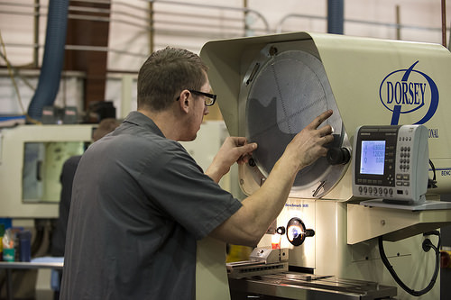
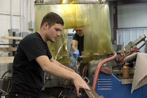
A handful of nice precision tool grinding photos I discovered:

Kerr Masonic Lodge No. 230 Barrie, Ontario – 2014 Kerr Entertaining Night – five
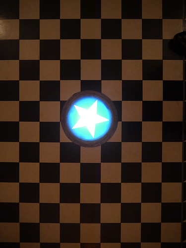
Image by antefixus21
Masonic Mosaic Pavement and Star.
The lodge space: www.flickr.com/pictures/21728045@N08/8101810367/in/set-7215…

www.masonicforum.ro/?cmd=displaystory&ampstory_id=73&ampamp….

The Mosaic Pavement
by GABRIEL VASILE OLTEAN
Professional Inspector of NGLR for Western Region Previous Worshipful Master, ZAMOLXIS Lodge, No. 182, Deva

&quotThe interior decoration of a masonic lodge comprises ornaments, accessories and insignia. The ornaments are: the mosaic on the floor – respresenting spirt and matter, the shining star and the laced edge, which remind us constantly the very first of the presence of God and the second of the protective wall&quot – cites Charles W Leadbeater from the ritual of mixed masonry in his operate &quotFreemasonry – Rites and Initiations.&quot
In the center of the Temple, on the ground, there is a rectangular floor, with black and white tiles, referred to as the mosaic pavement (theoretically, cubes observed perspectivally), where a relgaion obtains between the sides, either 2:1 (the extended square) or 1.618…/1 (the golden number), therefore coming up with a surface proportional to the total location of the Lodge. Hence we see that practically the moasica, placed in the center of the Lodge is a microcosmic representation of the whole of creation and is by itself a sacred central region – whence the interdiction to ever step on the mosaic when the operate of the Lodge is underway. The pavement symbolizes the indisociable operative complementarity of the two cosmic principles: the initiate should know how no longer let himself be dominated by the confrontation between constructive and unfavorable forces, to know (it is indispensable) how to use it, to master it so as to function constructively.
In Ancient Egypt, the mosaic was in no way stepped on except by a candidate and the masters of ceremony, and only at precise moments (by the Previous Worshipful Master for the fulfilment of his tasks, by the 1st Expert when he took the light of the sacred fire, or by the sexton when he spread frankincense on the altar of the Temple. An very essential aspect of the mosaic pavement is that, getting placed in the middle of the Temple, framed by the three colonettes (which represent the Worshipful Master, the Senior and Junior Wardens), must be avoided by walking in a square, in a symbolic sense. The current of power cross the floor, some along the length, some along the width, in lines that remind of the warp of a canvas.
Upon opening the work, the Trestle Board is depicted on this pavement, which varies with the first 3 degrees. The mosaic pavement signifies various items according to the traditional mode of perform in the lodge, or the masonic rite employed.
The French Rite specifies that the pavement adorned the threshold of the geat porch of the Temple and showed that this is 1 of the ornaments of the Lodge, being the emblem of the intimate union amongst masons. Right here it was explained to the Apprentice that he &quotcould not stand on the mosaic pavement to contemplate the interior of the edifice&quot. This began above from the seventh step, as we can well conclude by an attentive study of the Trestle Boards of the initial two degrees.
The Rectified Scottish Rite speaks also small of this pavement, noting that &quotthe mosaic pavement adorns the threshold of the great veranda of the Temple. It covers the entry to the subterranean element of the Temple between the two columns, to a crypt that held holy idols and especially the pledge of the alliance among the chosen folks and the Creator: the Royal Ark (Ark of the Covenant).
The Ancient and Accepted Scottish Rite does not describe in any way this ornament. As to the decoration of the Lodge, it is stated nonetheless &quotthe floor of the lodge is the pavement in option black and white squares. When it is hence decorated, a pavement is accomplished wit the shape of a extended square, placed in the center of the Lodge, decorated on the model of the latter&quot.
The York Rite affirms that &quotthe mosaic pavement represents the floor of the Temple of Solomon&quot, obtaining the added laced edge. It is apparent enough that it is about a symbolic contribution in what regards the floor of the Lodge, because in the Bible the floor of the Temple is not described as an series of black and white squares: &quotand the floor of the Temple was made from cypress planks&quot (3 Kings six:15).
Whereas in the Emulation Rite (the Anglo-Saxon Rites are more precise in their descriptions) specifies that &quotthe mosaic pavement could rightly be considered the wondrous tiling of a freemason Lodge due to its diversity and regularity. As a result the diversity of beings and objects in the globe surfaces, as nicely the ensouled ones as these that are not&quot. In the complementary course of the Rite of Emulation (in the fifth element) it is specified: &quotour lodge is adorned with mosaic pavement to mark the uncertainty of all terrestrial vanities… as we step on this mosaic, our thought should return to the original thought that we imitate and act as honorable males and masons&quot. Mosaic pavement is presented as an image of faith, harmony, understanding..
Outdoors the definitions supplied by distinct masonic rites, the mosaic pavement might be approached below many aspect, two of which appear edifying to us:
• The floor of the Lodge,
• The route of squares for the tracing of planes,
When we method the mosaic pavement as floor of the Lodge, we are forced to distinguish between the pavement of operative and speculative Lodges.
In the first case, we specify that Lodges were normally annexes to the construction site, attached to the building on the Southern side of the Perform (to get much more light and to have the wall of the edifice for protection. It is very clear and evident that in this case no floor was imposed (nor would any be functional). The tiling that constitutes the mosaic is fragile in contradiction with the dimensions (weight) of the tools of freemasons (sledgehammers have been quite heavy). If we are speaking about a surface for permanent cutting and polishing of rock, we can simply picture that the floor of such a spot was permanently covered by fragments, remains, abrasive dust. Not in the final place, we must note the truth that mosaic was principally fixed in specially prepared mortar in which designs have been initial marked that etched the image or drawing that was the objective of the mosaic.
In the other method, that of the speculative Lodges, a symbolic rug laid in squares may be laid on the floor, or it could be develop from alternating black and white tiles, the choice getting that of the Lodge. The notionc of mosaic pavement can not be discussed prior to the appearance of Grand Lodges.
As a route of squares – as network of right angles – to trace planes is one more mode of approach distinct to operative lodges, which have to distinguish:
A directory route of the edifice that need to be understood following we describe the Medieval constructin internet site at the beginning of the operate: on a leveled and cleared surface (treated with charcoal), a scheme of the principal lines of the edifice was traced with the aid of a rope covered in chalk. There
are documents to this impact that attest the describe practice, which reminds of particular answers from the masonic catechism. To the question: &quothow do you serve your Master?&quot, there is the answer: &quotwith charcoal, chalk and clay&quot.
A technical help set of squares would be another variant of this method. An amenably arranged surface, spread in typical squares via lines traced for inumerable uses, the very first and most essential becoming that of assembly table. It also served to establish effortlessly a series of angles, in an approximate way that was sufficient for a mason (taking four divisions on a line, and on the perpendicular seven at one particular extremity, a reasaonbly 60° angle is obtained). In truth, we can picture the banal math copybook paper that has helped us trace with a lot more facility (and far more precision) the geometrical shapes that tortured (or did not) us in the geometry troubles in elementary college.
The black and white, chessboard-like pavement is therefore the mosaic pavement. In what pertains to the term &quotmosaic&quot, there are two diverse opinions, one particular refering to Moses and one particular to the approach of decoration. Every school has its pros and cons, far more or much less logical and valid.
&quotThe canvas of ours lives is a mixed thread, the good collectively with the bad&quot wrote Shakespeare. Something is characterized by a mixture of great and undesirable, light and shadow, joy and sadness, constructive and negative, yin and yang. What is very good for me may be poor for you, pleasure is generated by discomfort, etc.
Following the thread of the present Paper, we may say with certainty that the mosaic is not mart of the components of Judaic architecture and that the mosaic pavement is a contribution of modern speculative Masonry, operative lodges never ever possessing been squared this way. It is obvious that the current exposition is not and does not wish to be an exhaustive operate. It is a somewhat complicated method of an crucial symbol in the decoration of the masonic Temple and it wishes in fact to the a paper addressing an open question:
- The mosaic pavement is the floor of the Lodge (as the rituals take into account it) or is it the space restricted by the 3 pillars Energy, Wisdom, and Beauty?
A good believed accompanied by the triple brotherly accolade!

Copyright Forum Masonic
Nice Precision Grinding Services photos

Nice Precision Grinding Services photos

Check out these precision grinding services images:

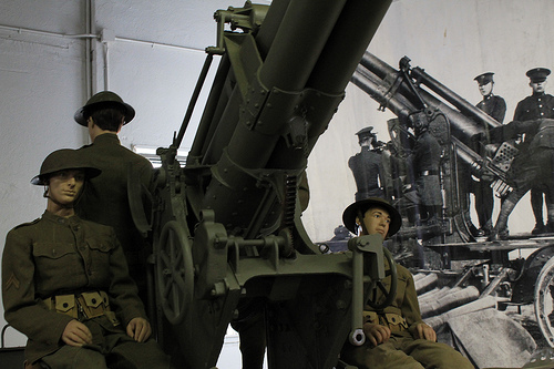
M1918 3-Inch Anti-Aircraft Gun

Image by Fidgit the Time Bandit
One display reads:

“The purpose of anti-aviation defense is to protect our own forces and establishments from hostile attack and observation from the air by keeping enemy aeroplanes at a distance.” – Brigadier General James A. Shipton, 1917

When the United States declared war on Germany in April 1917, we lagged far behind most nations in adopting Air Defense methods. Thrust into a conflict where new technologies like machine guns, chemical weaponry, tanks and airplanes had completely revolutionized warfare, the American Expeditionary Force was forced to modernize and adapt quickly.

On 26 July 1917, Brigadier General James Shipton and Captains Glenn Anderson and George Humbert left the United States with the first contingent of American combat troops destined for the Western Front. The three officers were tasked with observing both British and French anti-aircraft methods and establishing a new American Anti-Aircraft Service. While General Shipton coordinated with the British and French to acquire the necessary equipment for American air defense, Anderson and Humbert took the lead on researching Allied techniques. The two captains quickly determined that the French methods were far more effective. As a result, both attended the French Anti-aircraft school at Arnouville-les-Gonesse and upon completion established a co-located American school to instruct incoming American anti-aircraft officers and enlisted on the new doctrine.

Anderson and Humbert incorporated some effective British techniques, which resulted in the use of searchlights for locating enemy aircraft at night. Searchlights, coupled with acoustic locators like the French used allowed for better target acquisition and therefore better accuracy for both the heavy caliber and machine guns on target. The first American anti-aircraft class began in September 1917 and consisted of twenty-five officers.

The school was divided into two sections, focused on employing artillery and machine guns in the antiaircraft role. A third section, focused on searchlights, was created in January 1918. During its existence, the American Anti-aircraft school at Arnouville trained 578 officers and 12,000 enlisted in the employment of anti-aircraft systems of the day.

Using a mix of heavy guns, machine guns, sound locators and searchlights, American anti-aircraft units were able to better defend Allied positions and as a result, better engage enemy aircraft. By the time the Armistice ended World War I on November 11th 1918, the American Anti-aircraft Service had gone from an untested, cobbled-together organization to the most successful air defense arm in the world.

The next display reads:

WWI – Anti-Aircraft Machine Gun Battalions

With the establishment of the American Anti-aircraft School at Arnouville-les-Gonesse in October of 1917, the American Expeditionary Force had its own training program for anti-aircraft gunnery in Europe. The school trained US servicemen on the use of heavy guns, machine guns and searchlights. Five anti-aircraft batteries (75mm) and seven anti-aircraft machine gun battalions were activated during World War I. Of those seven machine gun battalions, only the 1st and 2nd Battalions saw combat; the remaining five battalions were either in training or in transit to Europe by the cessation of hostilities.

While the heavy gun batteries were focused on deterring enemy overflights of friendly territory, the machine gun battalions were tasked with directly engaging enemy aircraft. During their brief existence, the 1st and 2nd AA Machine Gun Battalions established a new standard for Allied anti-aircraft machine gun units. Firing just over 225,000 rounds of .30 caliber ammunition, the two battalions shot down 41 German airplanes; or one enemy airplane per 5,500 rounds. Allied statistics could only account for two enemy aircraft per 200,000 rounds by the end of World War I.

The official US kill tally by the end of the war stood at 58 confirmed airplanes shot down by both heavy guns and machine gun units. However, this fairly small number does not accurately reflect the performance of US anti-aircraft units. That figure did not include aircraft downed by American anti-aircraft troops serving on foreign equipment or with foreign units, where credit for the kill went to the higher Allied nation headquarters. Therefore, on 18 May 1918, while serving under the French Army, the 2nd Anti-aircraft Battery was not given credit for a kill, even though the unit shot down the US Anti-aircraft Service’s first airplane.

Despite the flawed kill confirmation process, the anti-aircraft machine gun battalions performed admirably both in the anti-aircraft and ground support roles, setting the standard of tactical flexibility that continues as a cornerstone of the Air Defense Artillery branch of the 21st Century.

Use of improvised anti-aircraft mounts were, like tree stumps, included in the AA machine gun training program.

The French Hotchkiss machine gun was one of the standard anti-aircraft weapons used by US forces on the Western Front.

Anti-aircraft machine guns became a necessity as World War I dragged on and aerial attacks on ground forces increased.

Acoustic locators enabled anti-aircraft units to detect inbound aircraft at greater distances, thereby giving gunners more time to bring their guns to bear on an inbound airplane.

Citation:

The President of the United States of America, authorized by Act of Congress, July 9, 1918, takes pleasure in presenting the Distinguished Service Cross to Second Lieutenant (Infantry) Samuel F. Telfair, United States Army, for extraordinary heroism in action while serving with the 2nd Anti-Aircraft Machine Gun Battalion, A.E.F., at Brieulles, France, on 4 November 1918. Second Lieutenant Telfair was leading a patrol to reconnoiter a position for anti-aircraft machine-guns when his group became scattered by intense shell fire. Upon returning to the shell-swept area to look for his patrol, he found one of the men severely wounded. Making two trips through the heavy shell fire he secured the assistance of Private Laurel B. Heath and carried the wounded soldier to safety.

Citation:

The President of the United States of America, authorized by Act of Congress, July 9, 1918, takes pleasure in presenting the Distinguished Service Cross to Sergeant Frank J. Gardella (ASN: 88892), United States Army, for extraordinary heroism in action while serving with Machine-Gun Company, 165th Infantry Regiment, 42d Division, A.E.F., north of the River Ourcq, near Villers-sur-Fere, France, 28 July 1918. When two enemy airplanes flew parallel to our Infantry lines north of the River Ourcq, pouring machine-gun bullets into our positions and driving everyone to cover, Sergeant Gardella rushed to his machine gun and took aim at the upper of the two machines. Although he was constantly subject to a storm of bullets from the planes and from enemy snipers on the ground, he nevertheless coolly sighted his gun and riddled the upper plane. It collapsed and fell in flames, striking the lower one as it fell and causing it to crash to the earth also.

The final display reads:

M1918 3-Inch Anti-Aircraft Gun

The M1918 3-Inch Anti-Aircraft Gun represents the culmination of combat experience in the First World War. The US had primarily used foreign-designed heavy guns like the M1897 “French 75” in the heavy gun anti-aircraft role during World War I, with a few M1917 fixed-position 3-inch guns arriving in theater very late in the war.

The Model 1918 3-Inch Anti-Aircraft Gun was the first US-manufactured, purpose-built, mobile anti-aircraft gun. An adaptation of the 3” Coast Artillery Gun, the M1918 had a high muzzle velocity (over 2,400 feet per second) and the new mount allowed for extremely high-angle fire. It completed testing in the Fall of 1918 and the first battery was rushed into service for trials on the Western Front.

Allied observers who viewed the Model 1918 3-Inch Anti-Aircraft Gun were extremely impressed with its performance. British and French efforts in this area were nothing more than mount adaptations of field guns. Those ad-hoc efforts, using weapons that failed to achieve a sufficiently short time of flight, were of limited effectiveness in actually engaging aircraft. The method of engagement had been dubbed “barrage fire” and relied on a wall of shrapnel at a predetermined altitude to deter enemy aircraft rather than precision targeting of individual aircraft. The high-velocity rounds of the M1918 changed that, and although fire control systems were still in their infancy, US anti-aircraft gunners now had a weapon they could use effectively.

There is some question as to whether the M1918 saw combat in World War I. Most sources show that the test guns did not get overseas until December 1918, a month after the Armistice was signed.

The M1918 soldiered on during the interwar years, serving as the primary weapon system for American Coast Artillery Anti-Aircraft units until its replacement, the M3 3-Inch Anti-Aircraft Gun began coming on line in 1928.

The last M1918 guns were phased out of service by 1932. Although production figures are vague, several hundred M1918 Guns were manufactured between 1918 and the early 1920s. Of those hundreds of early AA guns that defended American skies, only one now survives.

The Museum’s M1918 3” Gun was completely restored in 2013 and is as close to its original, operational configuration as possible.

Pointing the M1918 was a complex process, involving two gunners on each side to aim, traverse and elevate the gun.

Unlike earlier weapons that had been pressed into anti-aircraft service, the M1918 had a maximum elevation that was near-vertical, allowing for better target tracking.

Although heavy coastal defense guns were still the focus of the Coast Artillery Corps in the 1920s, anti-aircraft gun emplacements were quickly collocated to defend the heavy guns against potential air attack.

Taken December 13th, 2013.

Image from page 361 of “The origin and history of the primitive Methodist Church” (1880)

Image by Internet Archive Book Images
Identifier: originhistoryofp01kend
Title: The origin and history of the primitive Methodist Church
Year: 1880 (1880s)
Authors: Kendall, H. B
Subjects: Methodist Church — History
Publisher: London : Dalton
Contributing Library: University of California Libraries
Digitizing Sponsor: MSN

View Book Page: Book Viewer
About This Book: Catalog Entry
View All Images: All Images From Book

Click here to view book online to see this illustration in context in a browseable online version of this book.

Text Appearing Before Image:
MITIVE METHODIST CHURCH, * lircuit, and though Nottingham had its Circuit Committee, and Leicestershire was notwithout its capable officials, there was left a gap in discipline which the PreparatoryMeeting of 1819 was intended to supply. As to the separation of R. Winfield,growing out of his refusal to accept his appointment to Hull—that will moreappropriately be dealt with in our next chapter. The retirement of Benton must detain us a little while. Had he died, or emigrated,or seceded, our task would have been a simpler one. But he lived for thirty-eightyears after his retirement; and yet he became in a sense dead to Primitive Methodism.This is the fact that needs explanation. We are not specially prepared for this retire-ment by anything we have met with or observed. We might, possibly, have predictedthe retirement of Crawfoot; scarcely that of Benton. The event comes upon ussomewhat as a surprise, and we are almost ready to bring in the verdict—Silenced bythe visitation of God.

Text Appearing After Image:
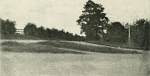
Kill M> Illl.L tAMI* MEETING SITE. In the month of .May, 1818,—two months after the opening of Leicester—a greatcamp meeting was held at Round Hill—a popular site for such gatherings. Withcharacteristic precision Hugh Bourne thus describes the position of Round Hill. Iti- an elevated piece of ground, about three and a half miles from Leicester, and issituated at the junction of the Roman Fosse Way with the Melton Turnpike Road.Time and place were favourable for a large gathering; and there was one. From everydirection people came, on fool and in vehicles of all kinds, until it was computed therewere ten thousand persons present. The meeting was well supported by preachers andpraying labourers. The morning service had been powerful, yet marked by decorum.At noon the converting work broke out, and the cries for mercy were loud andcontinuous. Benton was in great force; and as he spoke on the great day of Gods THE PERIOD OF CIRCUIT PREDOMINANCE AND ENTERPRISE. 353 wrath, and the

Note About Images
Please note that these images are extracted from scanned page images that may have been digitally enhanced for readability – coloration and appearance of these illustrations may not perfectly resemble the original work.

Lastest Centerless Grinding News

High-Precision Centerless Grinder Automatically Calculates Parameters
In the course of grinding, the regulating wheel presses the part against the grinding wheel profile at an angle, creating it achievable to grind highly complex components with numerous recesses, the organization says. The work rest blade can also be adjusted for the duration of the …
Study more on Modern Machine Shop

Enhancing titanium fastener output
Traditionally, aerospace fasteners go via centerless grinding to attain the required diameter. Utilizing 50-year-old technologies, most of these processes use infeed ground at the price of one particular piece per cycle. With fuel fees and other considerations …
Read a lot more on Aerospace Manufacturing and Design and style

Cool Turned Elements Manufacturer photos

Cool Turned Elements Manufacturer photos

Check out these turned components manufacturer images:

Steven F. Udvar-Hazy Center: principal hall panorama (SR-71, Space Shuttle, et al)

Image by Chris Devers
See far more images of this, and the Wikipedia article.

Information, quoting from Smithsonian National Air and Space Museum | Lockheed SR-71 Blackbird:

No reconnaissance aircraft in history has operated globally in far more hostile airspace or with such total impunity than the SR-71, the world’s fastest jet-propelled aircraft. The Blackbird’s overall performance and operational achievements placed it at the pinnacle of aviation technology developments during the Cold War.

This Blackbird accrued about 2,800 hours of flight time during 24 years of active service with the U.S. Air Force. On its final flight, March six, 1990, Lt. Col. Ed Yielding and Lt. Col. Joseph Vida set a speed record by flying from Los Angeles to Washington, D.C., in 1 hour, 4 minutes, and 20 seconds, averaging 3,418 kilometers (2,124 miles) per hour. At the flight’s conclusion, they landed at Washington-Dulles International Airport and turned the airplane more than to the Smithsonian.

Transferred from the United States Air Force.

Manufacturer:
Lockheed Aircraft Corporation

Designer:
Clarence L. &quotKelly&quot Johnson

Date:
1964

Nation of Origin:
United States of America

Dimensions:
General: 18ft five 15/16in. x 55ft 7in. x 107ft 5in., 169998.5lb. (5.638m x 16.942m x 32.741m, 77110.8kg)
Other: 18ft five 15/16in. x 107ft 5in. x 55ft 7in. (5.638m x 32.741m x 16.942m)

Supplies:
Titanium

Physical Description:
Twin-engine, two-seat, supersonic strategic reconnaissance aircraft airframe constructed largley of titanium and its alloys vertical tail fins are constructed of a composite (laminated plastic-sort material) to decrease radar cross-section Pratt and Whitney J58 (JT11D-20B) turbojet engines feature massive inlet shock cones.

• • • • •

See more photographs of this, and the Wikipedia report.

Specifics, quoting from Smithsonian National Air and Space Museum | Space Shuttle Enterprise:

Manufacturer:
Rockwell International Corporation

Nation of Origin:
United States of America

Dimensions:
General: 57 ft. tall x 122 ft. long x 78 ft. wing span, 150,000 lb.
(1737.36 x 3718.57 x 2377.44cm, 68039.6kg)

Supplies:
Aluminum airframe and physique with some fiberglass attributes payload bay doors are graphite epoxy composite thermal tiles are simulated (polyurethane foam) except for test samples of actual tiles and thermal blankets.

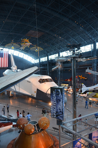
The 1st Space Shuttle orbiter, &quotEnterprise,&quot is a complete-scale test vehicle used for flights in the atmosphere and tests on the ground it is not equipped for spaceflight. Though the airframe and flight manage components are like those of the Shuttles flown in space, this car has no propulsion system and only simulated thermal tiles due to the fact these attributes have been not necessary for atmospheric and ground tests. &quotEnterprise&quot was rolled out at Rockwell International’s assembly facility in Palmdale, California, in 1976. In 1977, it entered service for a nine-month-extended approach-and-landing test flight program. Thereafter it was utilised for vibration tests and fit checks at NASA centers, and it also appeared in the 1983 Paris Air Show and the 1984 World’s Fair in New Orleans. In 1985, NASA transferred &quotEnterprise&quot to the Smithsonian Institution’s National Air and Space Museum.

Transferred from National Aeronautics and Space Administration

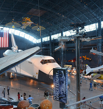
Steven F. Udvar-Hazy Center: Space exhibit panorama (Space Shuttle Enterprise)

Steven F. Udvar-Hazy Center: Space exhibit panorama (Space Shuttle Enterprise)

Check out these surface grinding stainless steel images:

Steven F. Udvar-Hazy Center: Space exhibit panorama (Space Shuttle Enterprise)

Image by Chris Devers
See a lot more photos of this, and the Wikipedia report.

Specifics, quoting from Smithsonian National Air and Space Museum | Space Shuttle Enterprise:

Manufacturer:
Rockwell International Corporation

Nation of Origin:
United States of America

Dimensions:
All round: 57 ft. tall x 122 ft. extended x 78 ft. wing span, 150,000 lb.
(1737.36 x 3718.57 x 2377.44cm, 68039.6kg)

Components:
Aluminum airframe and physique with some fiberglass features payload bay doors are graphite epoxy composite thermal tiles are simulated (polyurethane foam) except for test samples of actual tiles and thermal blankets.

The first Space Shuttle orbiter, &quotEnterprise,&quot is a full-scale test vehicle utilised for flights in the atmosphere and tests on the ground it is not equipped for spaceflight. Though the airframe and flight manage components are like these of the Shuttles flown in space, this car has no propulsion method and only simulated thermal tiles since these characteristics had been not required for atmospheric and ground tests. &quotEnterprise&quot was rolled out at Rockwell International’s assembly facility in Palmdale, California, in 1976. In 1977, it entered service for a nine-month-lengthy method-and-landing test flight system. Thereafter it was used for vibration tests and fit checks at NASA centers, and it also appeared in the 1983 Paris Air Show and the 1984 World’s Fair in New Orleans. In 1985, NASA transferred &quotEnterprise&quot to the Smithsonian Institution’s National Air and Space Museum.

Transferred from National Aeronautics and Space Administration

• • •

Quoting from Wikipedia | Space Shuttle Enterprise:

The Space Shuttle Enterprise (NASA Orbiter Automobile Designation: OV-101) was the initial Space Shuttle orbiter. It was constructed for NASA as element of the Space Shuttle plan to execute test flights in the atmosphere. It was constructed with no engines or a functional heat shield, and was for that reason not capable of spaceflight.

Initially, Enterprise had been intended to be refitted for orbital flight, which would have made it the second space shuttle to fly soon after Columbia. Nonetheless, during the building of Columbia, details of the final style changed, particularly with regard to the weight of the fuselage and wings. Refitting Enterprise for spaceflight would have involved dismantling the orbiter and returning the sections to subcontractors across the country. As this was an high-priced proposition, it was determined to be less pricey to build Challenger around a physique frame (STA-099) that had been produced as a test post. Similarly, Enterprise was considered for refit to replace Challenger after the latter was destroyed, but Endeavour was built from structural spares alternatively.

Service

Construction started on the 1st orbiter on June four, 1974. Designated OV-101, it was initially planned to be named Constitution and unveiled on Constitution Day, September 17, 1976. A write-in campaign by Trekkies to President Gerald Ford asked that the orbiter be named following the Starship Enterprise, featured on the tv show Star Trek. Even though Ford did not mention the campaign, the president—who during World War II had served on the aircraft carrier USS&nbspMonterey&nbsp(CVL-26) that served with USS&nbspEnterprise&nbsp(CV-six)—said that he was &quotpartial to the name&quot and overrode NASA officials.

The design of OV-101 was not the same as that planned for OV-102, the initial flight model the tail was constructed differently, and it did not have the interfaces to mount OMS pods. A large number of subsystems—ranging from major engines to radar equipment—were not installed on this car, but the capacity to add them in the future was retained. As an alternative of a thermal protection method, its surface was primarily fiberglass.

In mid-1976, the orbiter was used for ground vibration tests, permitting engineers to evaluate data from an actual flight automobile with theoretical models.

On September 17, 1976, Enterprise was rolled out of Rockwell’s plant at Palmdale, California. In recognition of its fictional namesake, Star Trek creator Gene Roddenberry and most of the principal cast of the original series of Star Trek were on hand at the dedication ceremony.

Strategy and landing tests (ALT)

Principal write-up: Method and Landing Tests

On January 31, 1977, it was taken by road to Dryden Flight Research Center at Edwards Air Force Base, to commence operational testing.

Whilst at NASA Dryden, Enterprise was utilised by NASA for a variety of ground and flight tests intended to validate elements of the shuttle system. The initial nine-month testing period was referred to by the acronym ALT, for &quotApproach and Landing Test&quot. These tests incorporated a maiden &quotflight&quot on February 18, 1977 atop a Boeing 747 Shuttle Carrier Aircraft (SCA) to measure structural loads and ground handling and braking qualities of the mated technique. Ground tests of all orbiter subsystems had been carried out to verify functionality prior to atmospheric flight.

The mated Enterprise/SCA combination was then subjected to five test flights with Enterprise unmanned and unactivated. The purpose of these test flights was to measure the flight qualities of the mated mixture. These tests were followed with three test flights with Enterprise manned to test the shuttle flight control systems.

Enterprise underwent 5 totally free flights where the craft separated from the SCA and was landed below astronaut control. These tests verified the flight qualities of the orbiter style and had been carried out beneath several aerodynamic and weight configurations. On the fifth and final glider flight, pilot-induced oscillation problems had been revealed, which had to be addressed prior to the 1st orbital launch occurred.

On August 12, 1977, the space shuttle Enterprise flew on its own for the initial time.

Preparation for STS-1

Following the ALT program, Enterprise was ferried among numerous NASA facilities to configure the craft for vibration testing. In June 1979, it was mated with an external tank and strong rocket boosters (identified as a boilerplate configuration) and tested in a launch configuration at Kennedy Space Center Launch Pad 39A.

Retirement

With the completion of critical testing, Enterprise was partially disassembled to let specific elements to be reused in other shuttles, then underwent an international tour going to France, Germany, Italy, the United Kingdom, Canada, and the U.S. states of California, Alabama, and Louisiana (throughout the 1984 Louisiana World Exposition). It was also utilized to match-verify the never ever-used shuttle launch pad at Vandenberg AFB, California. Ultimately, on November 18, 1985, Enterprise was ferried to Washington, D.C., where it became home of the Smithsonian Institution.

Post-Challenger

Right after the Challenger disaster, NASA regarded as employing Enterprise as a replacement. Nonetheless refitting the shuttle with all of the needed gear necessary for it to be utilised in space was considered, but alternatively it was decided to use spares constructed at the identical time as Discovery and Atlantis to construct Endeavour.

Post-Columbia

In 2003, right after the breakup of Columbia for the duration of re-entry, the Columbia Accident Investigation Board carried out tests at Southwest Investigation Institute, which used an air gun to shoot foam blocks of similar size, mass and speed to that which struck Columbia at a test structure which mechanically replicated the orbiter wing leading edge. They removed a fiberglass panel from Enterprise’s wing to carry out analysis of the material and attached it to the test structure, then shot a foam block at it. Whilst the panel was not broken as a result of the test, the influence was sufficient to permanently deform a seal. As the reinforced carbon-carbon (RCC) panel on Columbia was 2.five times weaker, this suggested that the RCC major edge would have been shattered. Further tests on the fiberglass have been canceled in order not to danger damaging the test apparatus, and a panel from Discovery was tested to establish the effects of the foam on a similarly-aged RCC top edge. On July 7, 2003, a foam effect test developed a hole 41&nbspcm by 42.5&nbspcm (16.1&nbspinches by 16.7&nbspinches) in the protective RCC panel. The tests clearly demonstrated that a foam influence of the variety Columbia sustained could seriously breach the protective RCC panels on the wing major edge.

The board determined that the probable trigger of the accident was that the foam impact caused a breach of a reinforced carbon-carbon panel along the top edge of Columbia’s left wing, permitting hot gases generated in the course of re-entry to enter the wing and cause structural collapse. This brought on Columbia to spin out of manage, breaking up with the loss of the whole crew.

Museum exhibit

Enterprise was stored at the Smithsonian’s hangar at Washington Dulles International Airport just before it was restored and moved to the newly constructed Smithsonian’s National Air and Space Museum‘s Steven F. Udvar-Hazy Center at Dulles International Airport, where it has been the centerpiece of the space collection. On April 12, 2011, NASA announced that Space Shuttle Discovery, the most traveled orbiter in the fleet, will be added to the collection after the Shuttle fleet is retired. When that takes place, Enterprise will be moved to the Intrepid Sea-Air-Space Museum in New York City, to a newly constructed hangar adjacent to the museum. In preparation for the anticipated relocation, engineers evaluated the automobile in early 2010 and determined that it was safe to fly on the Shuttle Carrier Aircraft once again.

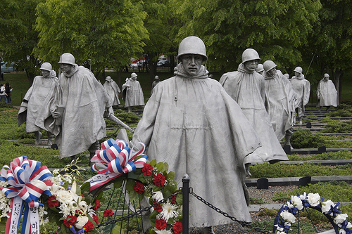
Korean War Memorial

Image by StarrGazr
From 1950 to 1953, the United States joined with the United Nations forces in Korea to take a stand against what was deemed a threat to democratic nations worldwide. At war’s end, a million and a half American veterans returned to a peacetime planet of households, houses, and jobs – and to a country long reluctant to view the Korean War as anything to memorialize. But to the men and females who served, the Korean War could never ever be a forgotten war.
The passing of more than four decades has brought a new perspective to the war and its aftermath. The time has come, in the eyes of the Nation, to set aside a location of remembrance for the people who served in this hard-fought war half a planet away. The Korean War Veterans Memorial honors these Americans who answered the get in touch with, these who worked and fought beneath the most attempting circumstances, and these who gave their lives for the lead to of freedom.

A War Half a Globe Away

Only 5 years had passed since the finish of Planet War II when the United States as soon as once more located itself embroiled in a key international conflict. In the early morning hours of June 25, 1950, the communist government of North Korea launched an attack into South Korea. Determined to help the world’s imperiled democracies, the United States immediately sent troops from Japan to join those already stationed in Korea they fought with other nations below the U.N. flag. What was envisioned as a brief, decisive campaign became a prolonged, bitter, frustrating fight that threatened to explode beyond Korean borders. For three years the fighting raged. In 1953 an uneasy peace returned by implies of a negotiated settlement that established a new boundary near the original one at the 38th parallel.
One particular-and-a-half million American guys and ladies, a true cross-section of the Nation’s populace, struggled side by side for the duration of the conflict. They served as soldiers, chaplains, nurses, clerks, and in a host of other combat and support roles. Several risked their lives in extraordinary acts of heroism. Of these, 131 received the Congressional Medal of Honor, the Nation’s most esteemed tribute for combat bravery.

A Place for Reflection

Viewed from above, the memorial is a circle interesected by a triangle. Visitors approaching the memorial come first to the triangular Field of Service. Right here, a group of 19 stainless-steel statues, produced by Globe War II veteran Frank Gaylord, depicts a squad on patrol and evokes the encounter of American ground troops in Korea. Strips of granite and scrubby juniper bushes suggest the rugged Korean terrain, even though windblown ponchos recall the harsh climate. This symbolic patrol brings with each other members of the U.S. Air Force, Army, Marines, and Navy the males portrayed are from a selection of ethnic backgrounds.
A granite curb on the north side of the statues lists the 22 countries of the United Nations that sent troops or gave healthcare assistance in defense of South Korea. On the south side is a black granite wall. Its polished surface mirrors the statues, intermingling the reflected images with the faces etched into the granite. The etched mural is primarily based on actual photographs of unidentified American soldiers, sailors, airmen, and marines. The faces represent all these who offered help for the ground troops. Collectively these pictures reflect the determination of U.S. forces and the countless techniques in which Americans answered their country’s contact to duty.

The adjacent Pool of Remembrance, encircled by a grove of trees, provides a quiet setting. Numbers of those killed, wounded, missing in action, and held prisoner-of-war are etched in stone nearby. Opposite this counting of the war’s toll another granite wall bears a message inlaid in silver:
Freedom Is Not Cost-free.

Establishment and Dedication

On October 28, 1986, Congress authorized the American Battle Monuments Commission to establish a memorial in Washington, D.C., to honor members of the U.S. armed forces who served in the Korean War. The Korean War Veterans Memorial Advisory Board was appointed by President Ronald Reagan to suggest a internet site and style, and to raise building funds. Ground was broken in November 1993. Frank Gaylord was selected as the principal sculptor of the statues and Louis Nelson was chosen to create the mural of etched faces on the wall. On July 27, 1995, the 42nd anniversary of the armistice that ended the Korean War, the memorial was devoted by President William J. Clinton and Kim Young Sam, President of the Republic of Korea.

Going to the Memorial

The memorial is staffed from eight a.m. to midnight each and every day of the year except December 25 by park rangers who are obtainable to answer inquiries and give talks. A bookstore in the nearby Lincoln Memorial sells informational products relating to both the memorial and the Korean War.
The Korean War Veterans Memorial is element of the National Park Technique, one of a lot more than 370 parks representing our nation’s all-natural and cultural heritage. Address inqueries to: Superintendent, National Capital Parks-Central, 900 Ohio Drive, SW, Washington, DC 20024-2000.

Homes on the hill

Homes on the hill

Some cool machining turning images:

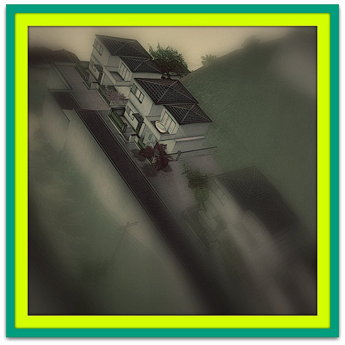
Houses on the hill

Image by ▓▒░ TORLEY ░▒▓
Ultra! Ultra! Study all about it!

Winch

Image by erroltookaphoto
An old boat winch to pull in fishing boats in from the sea. Sitting on the beach all year barely being employed has seen it worn away.

At the finish of the summer, the neighbors asked me to support pull in a single of the fishing boats with this ancient machine. I never realised how heavy a boat actually was until I located myself single handedly turning the crank on this issue.

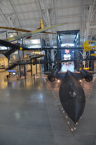
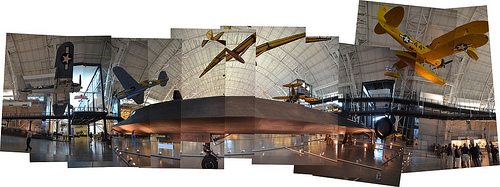
Steven F. Udvar-Hazy Center: Photomontage of SR-71 on the port side

Steven F. Udvar-Hazy Center: Photomontage of SR-71 on the port side

A handful of nice surface grinding aluminum photos I found:

Steven F. Udvar-Hazy Center: Photomontage of SR-71 on the port side

Image by Chris Devers
Posted by way of e-mail to ☛ HoloChromaCinePhotoRamaScope‽: cdevers.posterous.com/panoramas-of-the-sr-71-blackbird-at…. See the full gallery on Posterous …

• • • • •

See a lot more images of this, and the Wikipedia post.

Details, quoting from Smithsonian National Air and Space Museum | Lockheed SR-71 Blackbird:

No reconnaissance aircraft in history has operated globally in a lot more hostile airspace or with such comprehensive impunity than the SR-71, the world’s quickest jet-propelled aircraft. The Blackbird’s efficiency and operational achievements placed it at the pinnacle of aviation technology developments throughout the Cold War.

This Blackbird accrued about 2,800 hours of flight time for the duration of 24 years of active service with the U.S. Air Force. On its final flight, March 6, 1990, Lt. Col. Ed Yielding and Lt. Col. Joseph Vida set a speed record by flying from Los Angeles to Washington, D.C., in 1 hour, 4 minutes, and 20 seconds, averaging 3,418 kilometers (2,124 miles) per hour. At the flight’s conclusion, they landed at Washington-Dulles International Airport and turned the airplane over to the Smithsonian.

Transferred from the United States Air Force.

Manufacturer:
Lockheed Aircraft Corporation

Designer:
Clarence L. &quotKelly&quot Johnson

Date:
1964

Nation of Origin:
United States of America

Dimensions:
All round: 18ft five 15/16in. x 55ft 7in. x 107ft 5in., 169998.5lb. (5.638m x 16.942m x 32.741m, 77110.8kg)
Other: 18ft 5 15/16in. x 107ft 5in. x 55ft 7in. (5.638m x 32.741m x 16.942m)

Components:
Titanium

Physical Description:
Twin-engine, two-seat, supersonic strategic reconnaissance aircraft airframe constructed largley of titanium and its alloys vertical tail fins are constructed of a composite (laminated plastic-type material) to minimize radar cross-section Pratt and Whitney J58 (JT11D-20B) turbojet engines function huge inlet shock cones.

Long Description:
No reconnaissance aircraft in history has operated in more hostile airspace or with such full impunity than the SR-71 Blackbird. It is the fastest aircraft propelled by air-breathing engines. The Blackbird’s performance and operational achievements placed it at the pinnacle of aviation technologies developments throughout the Cold War. The airplane was conceived when tensions with communist Eastern Europe reached levels approaching a complete-blown crisis in the mid-1950s. U.S. military commanders desperately required precise assessments of Soviet worldwide military deployments, particularly near the Iron Curtain. Lockheed Aircraft Corporation’s subsonic U-2 (see NASM collection) reconnaissance aircraft was an able platform but the U. S. Air Force recognized that this fairly slow aircraft was currently vulnerable to Soviet interceptors. They also understood that the fast development of surface-to-air missile systems could put U-two pilots at grave threat. The danger proved reality when a U-2 was shot down by a surface to air missile over the Soviet Union in 1960.

Lockheed’s initial proposal for a new higher speed, higher altitude, reconnaissance aircraft, to be capable of avoiding interceptors and missiles, centered on a design and style propelled by liquid hydrogen. This proved to be impracticable simply because of considerable fuel consumption. Lockheed then reconfigured the design and style for conventional fuels. This was feasible and the Central Intelligence Agency (CIA), already flying the Lockheed U-two, issued a production contract for an aircraft designated the A-12. Lockheed’s clandestine ‘Skunk Works’ division (headed by the gifted style engineer Clarence L. &quotKelly&quot Johnson) developed the A-12 to cruise at Mach 3.two and fly well above 18,288 m (60,000 feet). To meet these difficult requirements, Lockheed engineers overcame a lot of daunting technical challenges. Flying far more than three instances the speed of sound generates 316° C (600° F) temperatures on external aircraft surfaces, which are adequate to melt standard aluminum airframes. The style group chose to make the jet’s external skin of titanium alloy to which shielded the internal aluminum airframe. Two standard, but extremely effective, afterburning turbine engines propelled this exceptional aircraft. These energy plants had to operate across a large speed envelope in flight, from a takeoff speed of 334 kph (207 mph) to much more than 3,540 kph (2,200 mph). To avoid supersonic shock waves from moving inside the engine intake causing flameouts, Johnson’s group had to style a complicated air intake and bypass program for the engines.

Skunk Functions engineers also optimized the A-12 cross-section design and style to exhibit a low radar profile. Lockheed hoped to attain this by carefully shaping the airframe to reflect as tiny transmitted radar energy (radio waves) as attainable, and by application of particular paint designed to absorb, rather than reflect, those waves. This treatment became one particular of the very first applications of stealth technologies, but it never totally met the style objectives.

Test pilot Lou Schalk flew the single-seat A-12 on April 24, 1962, following he became airborne accidentally in the course of high-speed taxi trials. The airplane showed great promise but it required considerable technical refinement prior to the CIA could fly the first operational sortie on May possibly 31, 1967 – a surveillance flight more than North Vietnam. A-12s, flown by CIA pilots, operated as portion of the Air Force’s 1129th Specific Activities Squadron beneath the &quotOxcart&quot program. While Lockheed continued to refine the A-12, the U. S. Air Force ordered an interceptor version of the aircraft designated the YF-12A. The Skunk Performs, nevertheless, proposed a &quotspecific mission&quot version configured to conduct post-nuclear strike reconnaissance. This system evolved into the USAF’s familiar SR-71.

Lockheed built fifteen A-12s, which includes a specific two-seat trainer version. Two A-12s have been modified to carry a particular reconnaissance drone, designated D-21. The modified A-12s have been redesignated M-21s. These have been designed to take off with the D-21 drone, powered by a Marquart ramjet engine mounted on a pylon among the rudders. The M-21 then hauled the drone aloft and launched it at speeds high enough to ignite the drone’s ramjet motor. Lockheed also built 3 YF-12As but this kind in no way went into production. Two of the YF-12As crashed in the course of testing. Only 1 survives and is on show at the USAF Museum in Dayton, Ohio. The aft section of one particular of the &quotwritten off&quot YF-12As which was later employed along with an SR-71A static test airframe to manufacture the sole SR-71C trainer. 1 SR-71 was lent to NASA and designated YF-12C. Which includes the SR-71C and two SR-71B pilot trainers, Lockheed constructed thirty-two Blackbirds. The initial SR-71 flew on December 22, 1964. Because of extreme operational fees, military strategists decided that the far more capable USAF SR-71s need to replace the CIA’s A-12s. These have been retired in 1968 soon after only 1 year of operational missions, mainly over southeast Asia. The Air Force’s 1st Strategic Reconnaissance Squadron (portion of the 9th Strategic Reconnaissance Wing) took more than the missions, flying the SR-71 beginning in the spring of 1968.

Right after the Air Force began to operate the SR-71, it acquired the official name Blackbird– for the unique black paint that covered the airplane. This paint was formulated to absorb radar signals, to radiate some of the tremendous airframe heat generated by air friction, and to camouflage the aircraft against the dark sky at high altitudes.

Knowledge gained from the A-12 system convinced the Air Force that flying the SR-71 safely necessary two crew members, a pilot and a Reconnaissance Systems Officer (RSO). The RSO operated with the wide array of monitoring and defensive systems installed on the airplane. This gear included a sophisticated Electronic Counter Measures (ECM) technique that could jam most acquisition and targeting radar. In addition to an array of sophisticated, high-resolution cameras, the aircraft could also carry equipment designed to record the strength, frequency, and wavelength of signals emitted by communications and sensor devices such as radar. The SR-71 was made to fly deep into hostile territory, avoiding interception with its tremendous speed and high altitude. It could operate safely at a maximum speed of Mach 3.3 at an altitude more than sixteen miles, or 25,908 m (85,000 ft), above the earth. The crew had to put on stress suits comparable to these worn by astronauts. These suits were essential to shield the crew in the event of sudden cabin stress loss although at operating altitudes.

To climb and cruise at supersonic speeds, the Blackbird’s Pratt &amp Whitney J-58 engines had been made to operate constantly in afterburner. Even though this would appear to dictate high fuel flows, the Blackbird truly accomplished its very best &quotgas mileage,&quot in terms of air nautical miles per pound of fuel burned, during the Mach 3+ cruise. A typical Blackbird reconnaissance flight might require many aerial refueling operations from an airborne tanker. Each time the SR-71 refueled, the crew had to descend to the tanker’s altitude, typically about six,000 m to 9,000 m (20,000 to 30,000 ft), and slow the airplane to subsonic speeds. As velocity decreased, so did frictional heat. This cooling impact triggered the aircraft’s skin panels to shrink considerably, and these covering the fuel tanks contracted so considerably that fuel leaked, forming a distinctive vapor trail as the tanker topped off the Blackbird. As quickly as the tanks were filled, the jet’s crew disconnected from the tanker, relit the afterburners, and again climbed to higher altitude.

Air Force pilots flew the SR-71 from Kadena AB, Japan, throughout its operational career but other bases hosted Blackbird operations, also. The 9th SRW sometimes deployed from Beale AFB, California, to other places to carryout operational missions. Cuban missions had been flown straight from Beale. The SR-71 did not begin to operate in Europe until 1974, and then only temporarily. In 1982, when the U.S. Air Force primarily based two aircraft at Royal Air Force Base Mildenhall to fly monitoring mission in Eastern Europe.

When the SR-71 became operational, orbiting reconnaissance satellites had already replaced manned aircraft to collect intelligence from sites deep inside Soviet territory. Satellites could not cover each geopolitical hotspot so the Blackbird remained a important tool for global intelligence gathering. On numerous occasions, pilots and RSOs flying the SR-71 offered data that proved crucial in formulating successful U. S. foreign policy. Blackbird crews provided crucial intelligence about the 1973 Yom Kippur War, the Israeli invasion of Lebanon and its aftermath, and pre- and post-strike imagery of the 1986 raid conducted by American air forces on Libya. In 1987, Kadena-primarily based SR-71 crews flew a quantity of missions more than the Persian Gulf, revealing Iranian Silkworm missile batteries that threatened commercial shipping and American escort vessels.

As the overall performance of space-primarily based surveillance systems grew, along with the effectiveness of ground-based air defense networks, the Air Force started to lose enthusiasm for the expensive plan and the 9th SRW ceased SR-71 operations in January 1990. Despite protests by military leaders, Congress revived the program in 1995. Continued wrangling more than operating budgets, even so, soon led to final termination. The National Aeronautics and Space Administration retained two SR-71As and the a single SR-71B for high-speed investigation projects and flew these airplanes till 1999.

On March 6, 1990, the service career of a single Lockheed SR-71A Blackbird ended with a record-setting flight. This special airplane bore Air Force serial number 64-17972. Lt. Col. Ed Yeilding and his RSO, Lieutenant Colonel Joseph Vida, flew this aircraft from Los Angeles to Washington D.C. in 1 hour, four minutes, and 20 seconds, averaging a speed of 3,418 kph (two,124 mph). At the conclusion of the flight, ‘972 landed at Dulles International Airport and taxied into the custody of the Smithsonian’s National Air and Space Museum. At that time, Lt. Col. Vida had logged 1,392.7 hours of flight time in Blackbirds, much more than that of any other crewman.

This particular SR-71 was also flown by Tom Alison, a former National Air and Space Museum’s Chief of Collections Management. Flying with Detachment 1 at Kadena Air Force Base, Okinawa, Alison logged a lot more than a dozen ‘972 operational sorties. The aircraft spent twenty-four years in active Air Force service and accrued a total of 2,801.1 hours of flight time.

Wingspan: 55’7&quot
Length: 107’5&quot
Height: 18’6&quot
Weight: 170,000 Lbs

Reference and Further Reading:

Crickmore, Paul F. Lockheed SR-71: The Secret Missions Exposed. Oxford: Osprey Publishing, 1996.

Francillon, Rene J. Lockheed Aircraft Since 1913. Annapolis, Md.: Naval Institute Press, 1987.

Johnson, Clarence L. Kelly: More Than My Share of It All. Washington D.C.: Smithsonian Institution Press, 1985.

Miller, Jay. Lockheed Martin’s Skunk Functions. Leicester, U.K.: Midland Counties Publishing Ltd., 1995.

Lockheed SR-71 Blackbird curatorial file, Aeronautics Division, National Air and Space Museum.

DAD, 11-11-01

Nice Precision Grinding photographs

Nice Precision Grinding photographs

Some cool precision grinding images:

Round four – Mullingar Road League 2014

Image by Peter Mooney
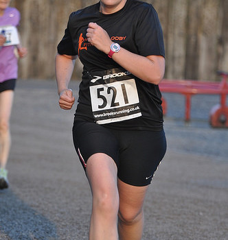
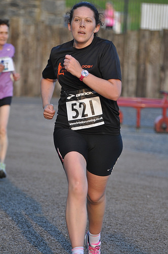
This is a photograph from the 4th and final round of the Mullingar Road League which was held in Belvedere Property and Gardens, Mullingar, Co. Westmeath, Ireland on Wednesday 28th Might 2014 at 20:00. This was the final race in the 2014 series. A music festival had been held in the grounds of Belvedere House on the preceding weekend and there was concerns that the race tonight would have to be moved outdoors the gardens. Nonetheless the ground-staff and Mullingar Harriers worked challenging to make certain that the race could go ahead and stick to it’s regular route. The race follows the roads and trails around Belvedere and is a very testing 5KM route. The race is promoted by Mullingar Harriers for the Pat Finnerty Memorial Cup. Competitors require to run three races out of the four races in May (any order) to be regarded in the overall placing in categories at the conclusion of the league. More than 350 folks took portion in tonight’s occasion. The climate was completely summery with lovely warm sunshine with tiny or no breeze. Excellent operating situations. The presentations for the end of the league and a vast array of refreshments were offered afterwards in the Cafe. Runners have been able to keep around and chat in the evening sunshine. The Mullingar Road League 2014 will go down as an additional accomplishment in the history of this fantastic series.

We have an substantial set of photographs from today in the following Flickr Album: www.flickr.com/pictures/peterm7/sets/72157644840050706/

Timing and event management was offered by Precision Timing. Final results are accessible on their site at www.precisiontiming.net/result/racetimer with additional material available on their Facebook page (www.facebook.com/davidprecisiontiming?fref=ts) See their promotional video on YouTube: www.youtube.com/watch?v=c-7_TUVwJ6Q

Reading on a Smartphone or tablet? Don’t overlook to scroll down further to study far more about this race and see crucial Net links to other information about the race! You can also uncover out how to access and download these photographs.

Our photographs from Round 1 of the 2014 Road League on Flickr: www.flickr.com/photos/peterm7/sets/72157644508131856/
Our photographs from Round 2 of the 2014 Road League on Flickr: www.flickr.com/images/peterm7/sets/72157644261638039/
Our photographs from Round 3 of the 2014 Road League on Flickr: www.flickr.com/photographs/peterm7/sets/72157644769714481/
Road League 2014 Facebook Page: www.facebook.com/patfinnertyroadleague?fref=ts (Demands Facebook logon)
YouTube Video for the Promotion of the 2014 Road League: www.youtube.com/watch?v=KfvVVwrkgTM
A Vimeo Video for the Promotion of the 2013 Road League: vimeo.com/64875578
Our photographs from Round five of the 2013 Road League on Flickr: www.flickr.com/photographs/peterm7/sets/72157633794985503/
Our photographs from Round 4 of the 2013 Road League on Flickr: www.flickr.com/pictures/peterm7/sets/72157633604656368/
Our photographs from Round 3 of the 2013 Road League on Flickr: www.flickr.com/images/peterm7/sets/72157633470510535/
Our photographs from Round two of the 2013 Road League on Flickr: www.flickr.com/images/peterm7/sets/72157633451422506/
Our photographs from Round 1 of the 2013 Road League on Flickr: www.flickr.com/photographs/peterm7/sets/72157633397519242/
Belvedere Home and Gardens on Google Street View: goo.gl/maps/WWTgD
Chip Timing Results from Precision Timing: www.precisiontiming.net/result/racetimer
Belvedere Home and Gardens Website: www.belvedere-house.ie/
Mullingar Harriers Facebook Group Web page: www.facebook.com/groups/158535740855708/?fref=ts
Our Flickr Collection from Mullingar Road League 2012 (1,800 photographs) www.flickr.com/pictures/peterm7/collections/72157629780992768/
Our Flickr Collection from Mullingar Road League 2011 (820 photographs) www.flickr.com/photographs/peterm7/collections/72157626524444213/
Our Flickr Collection from Mullingar Road League 2010 (500 photographs) www.flickr.com/pictures/peterm7/collections/72157624051668808/
Our Flickr Collection from Mullingar Road League 2009 (250 photographs) www.flickr.com/photographs/peterm7/collections/72157617814884076/
Our Flickr Collection from Mullingar Road League 2008 (150 photographs) www.flickr.com/photos/peterm7/collections/72157605062152203/

Can I use these photographs straight from Flickr on my social media account(s)?

Yes – of course you can! Flickr gives numerous methods to share this and other photographs in this Flickr set. You can share to: e-mail, Facebook, Pinterest, Twitter, Tumblr, LiveJournal, and WordPress and Blogger weblog sites. Your mobile, tablet, or desktop device will also offer you you many various possibilities for sharing this photo page on your social media outlets.

We take these photographs as a hobby and as a contribution to the running neighborhood in Ireland. Our only &quotcost&quot is our request that if you are utilizing these pictures: (1) on social media websites such as Facebook, Tumblr, Pinterest, Twitter,LinkedIn, Google+, etc or (2) other internet sites, blogs, net multimedia, industrial/promotional material that you need to supply a hyperlink back to our Flickr page to attribute us.

This also extends the use of these photos for Facebook profile pictures. In these circumstances please make a separate wall or blog post with a hyperlink to our Flickr page. If you do not know how this need to be carried out for Facebook or other social media please e-mail us and we will be pleased to aid suggest how to link to us.

I want to download these images to my personal computer or device?

You can download the photographic image right here direct to your pc or device. This version is the low resolution internet-quality image. How to download will differ slight from device to device and from browser to browser. Nevertheless – look for a symbol with three dots ‘ooo’ or the hyperlink to ‘View/Download’ all sizes. When you click on either of these you will be presented with the selection to download the image. Remember just doing a correct-click and &quotsave target as&quot will not work on Flickr.

I want get complete resolution, print-good quality, copies of these photographs?

If you just need to have these photographs for on-line usage then they can be employed directly once you respect their Inventive Commons license and give a hyperlink back to our Flickr set if you use them. For offline usage and printing all of the photographs posted here on this Flickr set are accessible free of charge, at no cost, at complete image resolution.

Please e mail petermooney78 AT gmail DOT com with the links to the photographs you would like to receive a full resolution copy of. We also ask race organisers, media, and so on to ask for permission just before use of our photos for flyers, posters, and so forth. We reserve the correct to refuse a request.

In summary please keep in mind when requesting photographs from usIf you are using the photographs on-line all we ask is for you to give a hyperlink back to our Flickr set or Flickr pages. You will uncover the link above clearly outlined in the description text which accompanies this photograph. Taking these photographs and preparing them for on the internet posting does take a significant effort and time. We are not posting photographs to Flickr for industrial motives. If you genuinely like what we do please spread the link about your social media, send us an email, leave a comment beside the photographs, send us a Flickr e-mail, etc. If you are making use of the photographs in newspapers or magazines we ask that you mention where the original photograph came from.

I would like to contribute one thing for your photograph(s)?
A lot of folks offer you payment for our photographs. As stated above we do not charge for these photographs. We take these photographs as our contribution to the operating neighborhood in Ireland. If you really feel that the photograph(s) you request are excellent enough that you would take into account paying for their purchase from other photographic providers or in other circumstances we would recommend that you can give a donation to any of the excellent charities in Ireland who do work for Cancer Care or Cancer Analysis in Ireland.

We use Creative Commons Licensing for these photographs
We use the Inventive Commons Attribution-ShareAlike License for all our photographs right here in this photograph set. What does this imply in reality?
The explaination is quite basic.
Attribution– anybody making use of our photographs gives us an acceptable credit for it. This ensures that men and women are not taking our photographs and passing them off as their own. This typically just imply placing a link to our photographs somewhere on your site, weblog, or Facebook where other people can see it.
ShareAlike – any individual can use these photographs, and make alterations if they like, or incorporate them into a larger project, but they must make those modifications available back to the community beneath the very same terms.

Inventive Commons aims to encourage inventive sharing. See some examples of Inventive Commons photographs on Flickr: www.flickr.com/creativecommons/

I ran in the race – but my photograph does not seem here in your Flickr set! What offers?

As pointed out above we take these photographs as a hobby and as a voluntary contribution to the operating community in Ireland. Quite typically we have really ran in the identical race and then switched to photographer mode after we finished the race. Consequently, we feel that we have no obligations to capture a photograph of each participant in the race. Even so, we do attempt our very best to capture as numerous participants as possible. But this is occasionally not achievable for a selection of motives:

&nbsp&nbsp&nbsp&nbsp &#9658You had been hidden behind an additional participant as you passed our camera
&nbsp&nbsp&nbsp&nbsp &#9658Weather or lighting situations meant that we had some photographs with blurry content which we did not upload to our Flickr set
&nbsp&nbsp&nbsp&nbsp &#9658There have been as well a lot of people – some races attract thousands of participants and as amateur photographs we can’t hope to capture photographs of every person
&nbsp&nbsp&nbsp&nbsp &#9658We just missed you – sorry about that – we did our greatest!

You can email us petermooney78 AT gmail DOT com to enquire if we have a photograph of you which did not make the final Flickr selection for the race. But we cannot promise that there will be photograph there. As alternatives we advise you to get in touch with the race organisers to enquire if there have been (1) other photographs taking photographs at the race occasion or if (two) there had been specialist commercial sports photographers taking photographs which may have some photographs of you available for purchase. You may well discover some hyperlinks for further data above.

Don’t like your photograph here?
That is OK! We realize!

If, for any explanation, you are not happy or comfy with your picture appearing here in this photoset on Flickr then please email us at petermooney78 AT gmail DOT com and we will remove it as soon as possible. We give careful consideration to every photograph before uploading.

I want to inform folks about these excellent photographs!
Fantastic! Thank you! The ideal hyperlink to spread the word around is probably http://www.flickr.com/peterm7/sets

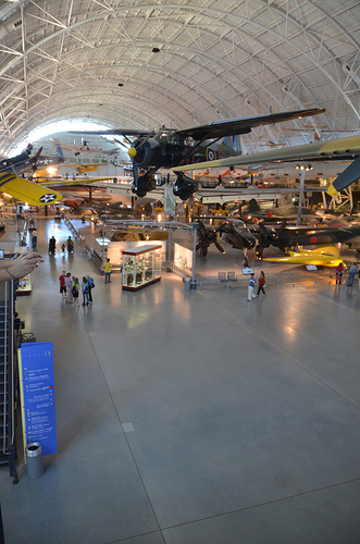
Steven F. Udvar-Hazy Center: major hall panorama

Image by Chris Devers
See far more images of this, and the Wikipedia write-up.

Particulars, quoting from Smithsonian National Air and Space Museum: Steven F. Udvar-Hazy | _specifics_pending_:

Cool Machined Components Manufacturers images

Cool Machined Components Manufacturers images

A handful of good machined components companies pictures I discovered:

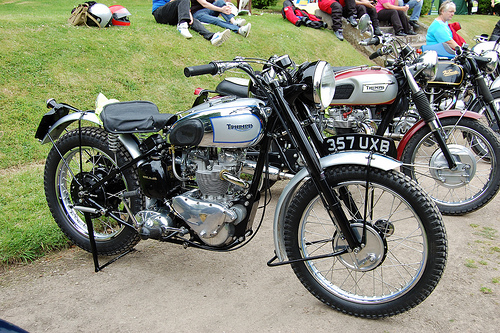
TRIUMPH TROPHY TR5. REAR IN HUB SUSPENSION. 500 CC TWIN CYLINDER.

Image by ronsaunders47
The Triumph TR5 Trophy was a British motorcycle produced by Triumph Motorcycles at their Meriden factory. Based on the Triumph Speed Twin, the TR5 was a trials machine created for off road use with a higher level two into a single exhaust and very good handling on public roads. [1] The name ‘Trophy’ came from the three ‘specials’ that Triumph built for the Italian International Six Day Trials in 1948, which went on to win 3 gold medals and the manufacturers group trophy.[two] Featuring prominently in the AMC &quotClass C&quot racing till 1969, the American export models included elements from rhe Triumph Tiger 100 to generate a motorcycle for desert competitors.[three]

From 1951 the 498cc engine (utilised as aircraft generators throughout World War II was updated with a new alloy barrels and heads. The TR5 was replaced with a new variety of unit building twins in 1959.[two] The Trophy name was resurrected for the Triumph TR6 Trophy in 1970 and the Trophy 500 (T100C) in 1971, which in turn was replaced by the Triumph Trophy Trail (TR5T) in 1973. The Hinckley Triumph organization employed the Trophy name for the Triumph Trophy 900 and Triumph Trophy 1200 models.

Renowned Riders
The Fonz , a character played by Henry Winkler in the well-known and lengthy operating American sit-com Pleased Days rode a Triumph TR5 Trophy. Both the character and bike were available as an MPC model kit in the 1970s.

In an attempt to ape Marlon Brando and his 6T Triumph Thunderbird, James Dean bought a Triumph TR5 Trophy. Phil Stern’s popular series of photographs of Dean show him upon this bike which although sold right after the actor’s untimely death, was recovered and restored prior to getting displayed at the James Dean Museum in Fairmount, Indiana.