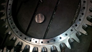
Klarm Machining, good choice for your CNC Program

M-codes are additionally used to turn coolant on and off in the machine. Coolant is typically turned on when the device rapids to the freedom plane and is normally killed toward the finish of a machining activity in china precision cnc titanium machining before an instrument change. The accompanying three coolant orders are normal:

M7 Mist coolant on

M8 Flood coolant on

M9 C oolant off

Not all machines will have the decision of fog or flood. They may just have one, so select the appropriate code for the given machine coolant framework type.

Numerous machines don’t permit a coolant code and a shaft code to be told together, since two M-codes are typically not permitted on a similar square.

A few machines get around this by permitting a M13 or a M114 code to both beginning the axle and turn the coolant on. This code doesn’t pick among flood and fog and will for the most part turn on the machine’s default coolant framework. Once more, check the machine’s manual to figure out which codes apply. In the event that a machine doesn’t acknowledge M13/M14, a different M7 or M8 order is typically customized in the square previously or after the shaft start. The coolant/shaft blend codes are:

M13 Spindle on clockwise with coolant

M14 Spindle on counterclockwise with coolant

Succession Numbers

Grouping numbers can be put toward the start of squares of code to fill in as a mark. They can be utilized for each square or irregularly all through the program to fill in as markers that help discover explicit segments of the program. Each arrangement number starts with an “N” character and they should increment through the program (e.g.. N2, N4, N6, N8, and so on; N5, N10, N15, N20; and so forth) The augmentations between numbers don’t make any difference on most machines as long as they are in expanding request. Numerous developers like to leave mathematical holes (N5, N10, N15, N20, and so on rather than N1, N2, N3, N4, and so on) so extra squares might be embedded if the program is altered later. Succession numbers are discretionary on most present day machines for standard tasks yet might be needed for certain high level activities. The program models in this unit wo exclude grouping numbers.

Finishing a Program in the Correct Format

After the program has been appropriately begun, various sorts of machining activities can be utilized to eliminate material from the workpiece. After all the material evacuation activities are done, the program will require a closure . That finishing initially withdraws the slicing apparatus to the leeway plane and turns off the coolant. Then, the shaft is paused and all machine tomahawks are moved to the machine home situations as when playing out an instrument change.

At that point one last square is required that contains just a M30 code. The M30 order closes the program and resets the program to its start. The program finishing squares may resemble this:

GO Z.1 (CLEAR PART IN Z);

M9 (COOLANT OFF);

G91 G28 Z0. M5 (RAPID TO MACHINE Z-HOME

Furthermore, SPINDLE OFF);

G91 G28 X0. YO. (Quick TO MACHINE XY-HOME);

M30 (END PROGRAM);

cnc machining metal parts suppliers china shows an illustration of a total program design for most Fanuc or Haas processing machines. This incorporates the program start data and program finishing data. Machining activities for material evacuation will be customized in the middle of the beginning and end and these tasks will be clarified all through the remainder of the unit. Survey china cnc stainless steel turning service manufacturers to see where all the data talked about so far finds a way into the CNC program.

This article is from http://www.tinymachining.com/
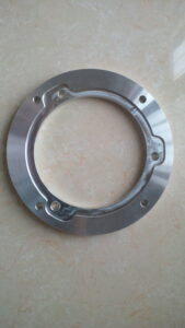
Rapid Traverse

Fast navigate developments should be performed cautiously in a CNC going machine to forestall crashes. Uncommon consideration should be paid to the shifting lengths of the cutting apparatuses and that they are so near other machine parts and the workpiece. Another thought is the area of the device before and toward the fruition of the fast developments. For example, if the instrument is an ID working apparatus, be certain it is withdrawn from the ID of the part preceding making a quick movement in the X-pivot or moving to a device change position. As an instrument moves toward the work, likewise be certain that there is a lot of leeway to forestall an impact. The cutting apparatus ought to never contact the workpiece during a quick navigate development.

Direct interjection synchronizes the movement of (at least one) tomahawks to move the instrument in an orderly fashion. For china precision machining parts suppliers to create a straight line, the machine should begin moving every hub at exactly a similar time, move them at the proper feed rate, and quit moving the two tomahawks at the objective simultaneously.

To move the apparatus in a direct way on a turning place, a G1 is told alongside the directions for the end position of the development. A feed rate should likewise go with the recently customized position. Machine feed rates are communicated in the G1 block with a F-character followed by a feed esteem. A feed rate order is modular and in the event that one isn’t customized in a square, at that point the last modified rate stays dynamic.

Feed rates for CNC turning can be in either inches every moment (IPM) or inches per upset (IPR). IPR is more normal for turning. A modular G-code should be modified to set the machine control to the proposed units. On numerous machines a G98 is utilized for IPM and G99 is utilized for IPR. It is a decent practice to incorporate the ideal setting for the feed rate units toward the start of the program in the protected beginning square. cnc machining turning parts manufacturers shows an illustration of a basic direct movement between two focuses and the comparing program code.

Roundabout Interpolation for Turning- – G2 and G3

CNC turning focuses can likewise make round movements (called bends) with the device tip for machining fillets and radi. To program a curve, the instrument should initially be situated toward the beginning point where that circular segment starts. Once there, a G-code is given to demonstrate whether the curve heading is clockwise or counterclockwise. On the off chance that the curve turns clockwise from begin to end, a G2 code is utilized. On the off chance that the bend turns counterclockwise, a G3 is utilized. On most turning habitats the cutting device is on the rear of the workpiece and a G2 will make a sunken range and a G3 will make a raised sweep (corner round).

cnc precision machining factory shows a marked illustration of the significant pieces of a circular segment. It is imperative to get comfortable with every one of these parts prior to programming. Preceding cutting the bend, the cutting instrument should be situated at the curve’s beginning stage with a standard G1 or GO. After the device is in position, the code for the curve course is given and the software engineer should recognize the end point where the bend stops (recollect that the instrument is now starting toward the beginning point). Data about the circular segment’s size should be given in a similar square of code. There are two strategies for programming the size of the circular segment: programming a span esteem and recognizing the bend’s middle point area.

This article is from http://www.tinymachining.com/
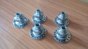
Cutting Tools

The entirety of the holemaking instruments for handheld electric drill applications may likewise be utilized by metal milling part manufacturers china in the drill press with the additional advantage of expanded force and control. Since there is impressively more force accessible, a workpiece being machined in a drill press must be safely mounted to forestall injury to the administrator. Before any machining cycle can start on the drill press, the cutting instruments must be appropriately mounted and the workpiece must be appropriately made sure about.

Fast steel (HSS) is well known because of its ease, and capacity to flex under effect without breaking or chipping. HSS can likewise be joined with other alloying fixings, for example, cobalt. Some slicing instruments may have up to 8% cobalt added to them. These HSS apparatuses are frequently marked as simply”cobalt.” This assortment of HSS offers similar preferences as standard HSS, however can work at up to 10% higher speeds and feeds because of its marginally higher hardness, better durability, wear obstruction, and warmth opposition.

Tungsten carbide is additionally a cutting-instrument material utilized for superior and high-creation tasks like custom precision cnc machining plastic parts china. Tungsten offers better apparatus life due than its outrageous hardness, wear opposition, and capacity to withstand heat. While carbide is acceptable at numerous things, it is additionally fragile, and effectively chipped under effect. While some tooling is made of strong carbide, more practical tooling is accessible that utilizes little bits of carbide as the instrument’s bleeding edges. The carbide pieces can either be mounted to the steel device body by brazing or by screws. Tooling utilizing replaceable carbide held precision machining made in china set up with screws is known as embedded or indexable tooling. Strong carbide apparatuses can be recognized from HSS cutting devices by weight. Since carbide is an extremely thick material carbide devices might be up to double the heaviness of comparable HSS cutting instruments. Numerous instruments being used today have surface coatings concerned them, for example, Titanium Nitride (TiN). An instrument that has been TiN covered will have a glossy gold appearance.

These coatings can additionally expand the life of the instrument. In its uncoated state carbide will show up as a more obscure, grayish shading rather than rapid steel’s brilliant, sparkly gloss or profound dark oxide finish.

Boring tools

The reason and capacity of a boring tool was canvassed gently; notwithstanding, there are some extra insights concerning a bore that are imperative to comprehend when the machining measures become additionally requesting.

Contort Drills

A contort drill can be separated into three principle parts: the drill point, drill body, and shank. Every one of these parts serves an imperative job.

The Drill Point

The drill point is the cone-formed zone at the very tip of the boring apparatus. The drill point is made of the accompanying sub-parts:

The lips are the calculated forefronts that shear the metal into chips as the drill pivots. The lips are the main aspect of the drill that really cuts. Each bend drill has two lips. The remembered edge of the lips for a broadly useful curve drill is 118 degrees. Other point edges may perform better when boring particular kinds of materials. On the off chance that the drill tip is inappropriately honed so one lip is longer than the other, the drill will cut bigger than its proposed size.

This article is from http://www.tinymachining.com