Check out these precision machining firm pictures:
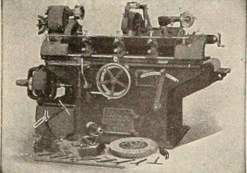
Image from web page 243 of “Canadian machinery and metalworking (January-June 1913)” (1913)
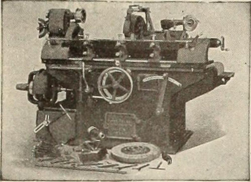
Image by Internet Archive Book Photos
Identifier: canmachinerjanjun1913toro
Title: Canadian machinery and metalworking (January-June 1913)
Year: 1913 (1910s)
Authors:
Subjects: Machinery Machinery Machinery
Publisher: Toronto MacLean-Hunter
Contributing Library: Fisher – University of Toronto
Digitizing Sponsor: Algoma University, Trent University, Lakehead University, Laurentian University, Nipissing University, Ryerson University and University of Toronto Libraries
View Book Web page: Book Viewer
About This Book: Catalog Entry
View All Pictures: All Images From Book
Click here to view book on the web to see this illustration in context in a browseable on the web version of this book.
Text Appearing Ahead of Image:
Grade Tools. Catalogue Ma/led on Application. Union Twist Drill Firm The Drill and Cutter Makers Athol, Mass., U.S.A. New York Store: 54 Warren St., E. W. McKeen. Boston Agents: 25 Obtain St., E. T. Ward & Sons. Philadelphia Shop: TheBourse. Chicago Store: 547 W. Washington Blvd., E. Lagerholm, Mgr. Foreign Agents: France, Alfred H. Schutte, 22-24 Ruede Petits Hotel, Paris. England: Chas. Neat & Co., 112 Queen Victoria St., London. Agents for Sweden: Wllh. Sonesson & Co.,Malmo, Stockholm and Gothenburg. Agents for Denmark, Norway and Finland: Aktieselskabet Wilh. Sonesson & Co., Copen-hagen City and Freeport, Australia Bevan & Edwards Pty., Ltd., 117-129 King St., Melbourne. Agents for Germany: Schmidt &Clemens, Frankfort a.M. Japan: Takata & Co., Yokohama. H. W. Petrie, Ltd., Toronto and Montreal, Canada. The advertiser would like to know exactly where you saw his advertisement—tell him. 16 CANADIAN MACHINERY Volume IX. LANDIS PRECISION GRINDING MACHINES
Text Appearing After Image:
Note About Images
Please note that these images are extracted from scanned web page images that could have been digitally enhanced for readability – coloration and appearance of these illustrations could not perfectly resemble the original perform.
Image from page 305 of “Railway and locomotive engineering : a practical journal of railway motive power and rolling stock” (1901)
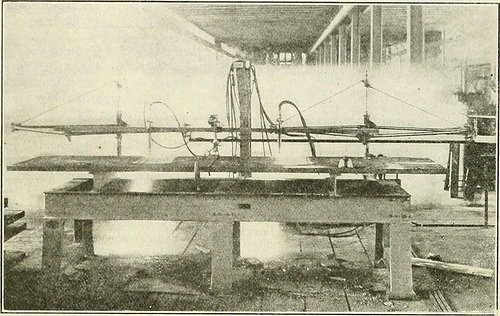
Image by Internet Archive Book Photos
Identifier: railwaylocomotiv29newy
Title: Railway and locomotive engineering : a sensible journal of railway motive energy and rolling stock
Year: 1901 (1900s)
Authors:
Subjects: Railroads Locomotives
Publisher: New York : A. Sinclair Co
Contributing Library: Carnegie Library of Pittsburgh
Digitizing Sponsor: Lyrasis Members and Sloan Foundation
View Book Web page: Book Viewer
About This Book: Catalog Entry
View All Pictures: All Photos From Book
Click right here to view book online to see this illustration in context in a browseable online version of this book.
Text Appearing Ahead of Image:
er examination. A prominent railroad manager attrib-utes his accomplishment in life to the spurring upto do anything for himself receivedfrom R.mlway and LocoMOTrvE Engin-eering. Do you want to advance and impro cyour condition? R.mlway and Locomo-Tm Engineering has helped many menand can support you. Its columns are complete oibright factors each and every month, and there i>nothing just as great published. Be sensible and send in your name with.00 to this workplace or give it to our nearestagent. 302 RAILWAY AND LOCOMOTIVE EXGINEEKIXG. ScptcmbiT, 1016. Oxy-Acetylene Welding and Cutting Illustrations of Operations and Fees Xo bctti-r illustration cniiUl be yiven ofthe adaptability of the use of the oxy-acetylene in cutting metals than in theappliance shown in Fig. 1. and identified asthe Oxy.yrapb. s inrlooted I, ibr types uf slotting machines. In additionto the machine as shown, it is equippedwith an electrically propelled rollingtri-icer, which can be guided along theliins of a drawing, and the cutting flame
Text Appearing Following Image:
l-JG. 1. EV Ol– O.XYGRAPH IN OPERATIOX. Davis-Bournunville Business it will reduce or flarncs will make an exact reproduc-steel many inches in thickness at the tion of one-half the dimensions of therate of from six to twelve inches per drawing. The cut m.ide Ijy the flame isminute. Its capacity is such that it read-ily replaces a number of of the most potent narrow and completely smooth, and themovement in curves or acute angles isperfect, and is of excellent benefit wher-ever steel is reduce in irregular forms. Themotor energy required to move the ap-paratus i.s- of the lightest sort, an electriclamp coimection or little battery beingsidVuient. -s shown in the illustration itma be furnished with a double panto-graph fraine, litted with two cuttingtorches for producing duplicate cuts at thesame time, and is particularly made lorheavy function. In point of precision itcannot be approaclied by hand work, asthe operator does not need to comenear the torch or torches, his work beingto guide the
Note About Images
Please note that these images are extracted from scanned page photos that might have been digitally enhanced for readability – coloration and appearance of these illustrations could not completely resemble the original perform.
Image from page 317 of “Illustrated catalogue and basic description of enhanced machine tools for working metal” (1899)
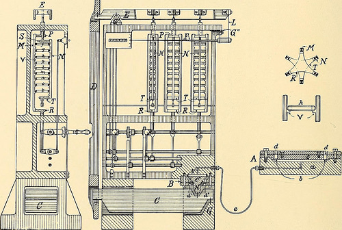
Image by Internet Archive Book Images
Identifier: illustratedcatal00sell
Title: Illustrated catalogue and general description of enhanced machine tools for working metal
Year: 1899 (1890s)
Authors: Sellers, William, & co. [from old catalog]
Subjects: Machine-tools Machinery
Publisher: Philadephia, Levytype organization
Contributing Library: The Library of Congress
Digitizing Sponsor: The Library of Congress
View Book Page: Book Viewer
About This Book: Catalog Entry
View All Photos: All Images From Book
Click right here to view book on the web to see this illustration in context in a browseable on the internet version of this book.
Text Appearing Ahead of Image:
HYDRAULIC-Assistance TESTING-MACHINE. Maximum Capacity, 500,000 lbs. Ratio from major weighing-platen to point of indicator needle in scale-case,300,000: I. Used for calibrating the hydraulic supports of all new testing ma-chines, and adjusting the poise weights with wonderful precision. Extremely sensi-tive, 200 grains on major platform will place in motion 20,000 lbs. of levers andplatforms, and deflect scale needle. No reduction of sensitiveness when fullyloaded. 312 Wm. Sellers & Co., Incorporated, Philadelphia, Pa. putting them on or taking them oflf, without having handling, is peculiar to the Emery-method. Suspended from this lever, E, at suitable intervals by thin fulcrumplates, are poise frames, N, consisting of an upper cross-head, ^, and a lowercross-head, T, united by three vertical bars disposed at equal intervals about thecross-heads. Fig. I.
Text Appearing Right after Image:
These bars are provided on their inner faces with quick projecting brackets,V, possessing a horizontal surface and a bevelled surface corresponding with similarsurfaces formed on the weights h, which are quick cylinders or rings with bevellededges the weights are carried by the flat surfaces and centred by the bevelledsurfaces. A weight-frame, M, for carrying the weights when not in use, ofsimilar building, has its 3 vertical bracketed bars alternating with the barsof the poise-frame this weight-frame is guided, and is raised and lowered in avertical line with out touching the poise-frame, b} a rock shaft and a hand-levercoupled to the rod projecting from the cross-head R. The brackets on the weight-frame bars are differently spaced from those on the poise-frame, and when theweight-frame is at the prime of its stroke, it carries all of the weights clear of thepoise-frame a little movement downwards transfers 1 weight to the poise-frame, the bevelled surfaces on the brackets ce
Note About Pictures
Please note that these images are extracted from scanned web page pictures that may possibly have been digitally enhanced for readability – coloration and look of these illustrations may not completely resemble the original function.
