Array
Cool
Cool Surface Grinding Manufacturer images
A few nice surface grinding manufacturer images I found:
Steven F. Udvar-Hazy Center: Space Shuttle Enterprise in the James McDonnell Space Hangar
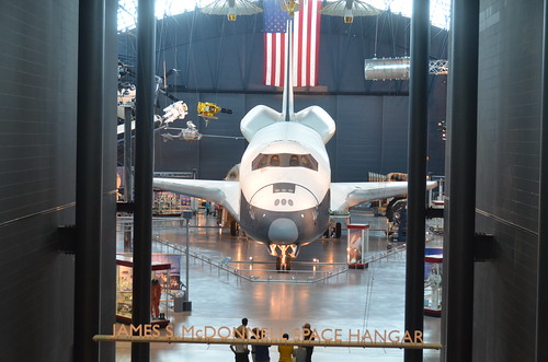
Image by Chris Devers
See more photos of this, and the Wikipedia article.
Details, quoting from Smithsonian National Air and Space Museum | Space Shuttle Enterprise:
Manufacturer:
Rockwell International Corporation
Country of Origin:
United States of America
Dimensions:
Overall: 57 ft. tall x 122 ft. long x 78 ft. wing span, 150,000 lb.
(1737.36 x 3718.57 x 2377.44cm, 68039.6kg)
Materials:
Aluminum airframe and body with some fiberglass features; payload bay doors are graphite epoxy composite; thermal tiles are simulated (polyurethane foam) except for test samples of actual tiles and thermal blankets.
The first Space Shuttle orbiter, "Enterprise," is a full-scale test vehicle used for flights in the atmosphere and tests on the ground; it is not equipped for spaceflight. Although the airframe and flight control elements are like those of the Shuttles flown in space, this vehicle has no propulsion system and only simulated thermal tiles because these features were not needed for atmospheric and ground tests. "Enterprise" was rolled out at Rockwell International’s assembly facility in Palmdale, California, in 1976. In 1977, it entered service for a nine-month-long approach-and-landing test flight program. Thereafter it was used for vibration tests and fit checks at NASA centers, and it also appeared in the 1983 Paris Air Show and the 1984 World’s Fair in New Orleans. In 1985, NASA transferred "Enterprise" to the Smithsonian Institution’s National Air and Space Museum.
Transferred from National Aeronautics and Space Administration
• • •
Quoting from Wikipedia | Space Shuttle Enterprise:
The Space Shuttle Enterprise (NASA Orbiter Vehicle Designation: OV-101) was the first Space Shuttle orbiter. It was built for NASA as part of the Space Shuttle program to perform test flights in the atmosphere. It was constructed without engines or a functional heat shield, and was therefore not capable of spaceflight.
Originally, Enterprise had been intended to be refitted for orbital flight, which would have made it the second space shuttle to fly after Columbia. However, during the construction of Columbia, details of the final design changed, particularly with regard to the weight of the fuselage and wings. Refitting Enterprise for spaceflight would have involved dismantling the orbiter and returning the sections to subcontractors across the country. As this was an expensive proposition, it was determined to be less costly to build Challenger around a body frame (STA-099) that had been created as a test article. Similarly, Enterprise was considered for refit to replace Challenger after the latter was destroyed, but Endeavour was built from structural spares instead.
Service
Construction began on the first orbiter on June 4, 1974. Designated OV-101, it was originally planned to be named Constitution and unveiled on Constitution Day, September 17, 1976. A write-in campaign by Trekkies to President Gerald Ford asked that the orbiter be named after the Starship Enterprise, featured on the television show Star Trek. Although Ford did not mention the campaign, the president—who during World War II had served on the aircraft carrier USS Monterey (CVL-26) that served with USS Enterprise (CV-6)—said that he was "partial to the name" and overrode NASA officials.
The design of OV-101 was not the same as that planned for OV-102, the first flight model; the tail was constructed differently, and it did not have the interfaces to mount OMS pods. A large number of subsystems—ranging from main engines to radar equipment—were not installed on this vehicle, but the capacity to add them in the future was retained. Instead of a thermal protection system, its surface was primarily fiberglass.
In mid-1976, the orbiter was used for ground vibration tests, allowing engineers to compare data from an actual flight vehicle with theoretical models.
On September 17, 1976, Enterprise was rolled out of Rockwell’s plant at Palmdale, California. In recognition of its fictional namesake, Star Trek creator Gene Roddenberry and most of the principal cast of the original series of Star Trek were on hand at the dedication ceremony.
Approach and landing tests (ALT)
Main article: Approach and Landing Tests
On January 31, 1977, it was taken by road to Dryden Flight Research Center at Edwards Air Force Base, to begin operational testing.
While at NASA Dryden, Enterprise was used by NASA for a variety of ground and flight tests intended to validate aspects of the shuttle program. The initial nine-month testing period was referred to by the acronym ALT, for "Approach and Landing Test". These tests included a maiden "flight" on February 18, 1977 atop a Boeing 747 Shuttle Carrier Aircraft (SCA) to measure structural loads and ground handling and braking characteristics of the mated system. Ground tests of all orbiter subsystems were carried out to verify functionality prior to atmospheric flight.
The mated Enterprise/SCA combination was then subjected to five test flights with Enterprise unmanned and unactivated. The purpose of these test flights was to measure the flight characteristics of the mated combination. These tests were followed with three test flights with Enterprise manned to test the shuttle flight control systems.
Enterprise underwent five free flights where the craft separated from the SCA and was landed under astronaut control. These tests verified the flight characteristics of the orbiter design and were carried out under several aerodynamic and weight configurations. On the fifth and final glider flight, pilot-induced oscillation problems were revealed, which had to be addressed before the first orbital launch occurred.
On August 12, 1977, the space shuttle Enterprise flew on its own for the first time.
Preparation for STS-1
Following the ALT program, Enterprise was ferried among several NASA facilities to configure the craft for vibration testing. In June 1979, it was mated with an external tank and solid rocket boosters (known as a boilerplate configuration) and tested in a launch configuration at Kennedy Space Center Launch Pad 39A.
Retirement
With the completion of critical testing, Enterprise was partially disassembled to allow certain components to be reused in other shuttles, then underwent an international tour visiting France, Germany, Italy, the United Kingdom, Canada, and the U.S. states of California, Alabama, and Louisiana (during the 1984 Louisiana World Exposition). It was also used to fit-check the never-used shuttle launch pad at Vandenberg AFB, California. Finally, on November 18, 1985, Enterprise was ferried to Washington, D.C., where it became property of the Smithsonian Institution.
Post-Challenger
After the Challenger disaster, NASA considered using Enterprise as a replacement. However refitting the shuttle with all of the necessary equipment needed for it to be used in space was considered, but instead it was decided to use spares constructed at the same time as Discovery and Atlantis to build Endeavour.
Post-Columbia
In 2003, after the breakup of Columbia during re-entry, the Columbia Accident Investigation Board conducted tests at Southwest Research Institute, which used an air gun to shoot foam blocks of similar size, mass and speed to that which struck Columbia at a test structure which mechanically replicated the orbiter wing leading edge. They removed a fiberglass panel from Enterprise’s wing to perform analysis of the material and attached it to the test structure, then shot a foam block at it. While the panel was not broken as a result of the test, the impact was enough to permanently deform a seal. As the reinforced carbon-carbon (RCC) panel on Columbia was 2.5 times weaker, this suggested that the RCC leading edge would have been shattered. Additional tests on the fiberglass were canceled in order not to risk damaging the test apparatus, and a panel from Discovery was tested to determine the effects of the foam on a similarly-aged RCC leading edge. On July 7, 2003, a foam impact test created a hole 41 cm by 42.5 cm (16.1 inches by 16.7 inches) in the protective RCC panel. The tests clearly demonstrated that a foam impact of the type Columbia sustained could seriously breach the protective RCC panels on the wing leading edge.
The board determined that the probable cause of the accident was that the foam impact caused a breach of a reinforced carbon-carbon panel along the leading edge of Columbia’s left wing, allowing hot gases generated during re-entry to enter the wing and cause structural collapse. This caused Columbia to spin out of control, breaking up with the loss of the entire crew.
Museum exhibit
Enterprise was stored at the Smithsonian’s hangar at Washington Dulles International Airport before it was restored and moved to the newly built Smithsonian’s National Air and Space Museum‘s Steven F. Udvar-Hazy Center at Dulles International Airport, where it has been the centerpiece of the space collection. On April 12, 2011, NASA announced that Space Shuttle Discovery, the most traveled orbiter in the fleet, will be added to the collection once the Shuttle fleet is retired. When that happens, Enterprise will be moved to the Intrepid Sea-Air-Space Museum in New York City, to a newly constructed hangar adjacent to the museum. In preparation for the anticipated relocation, engineers evaluated the vehicle in early 2010 and determined that it was safe to fly on the Shuttle Carrier Aircraft once again.
Steven F. Udvar-Hazy Center: Vought F4U-1D Corsair
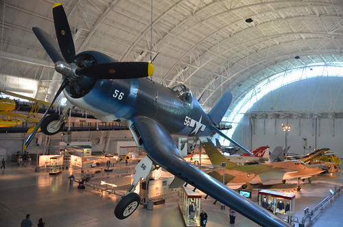
Image by Chris Devers
See more photos of this, and the Wikipedia article.
Details, quoting from Smithsonian National Air and Space Museum | Vought F4U-1D Corsair:
By V-J Day, September 2, 1945, Corsair pilots had amassed an 11:1 kill ratio against enemy aircraft. The aircraft’s distinctive inverted gull-wing design allowed ground clearance for the huge, three-bladed Hamilton Standard Hydromatic propeller, which spanned more than 4 meters (13 feet). The Pratt and Whitney R-2800 radial engine and Hydromatic propeller was the largest and one of the most powerful engine-propeller combinations ever flown on a fighter aircraft.
Charles Lindbergh flew bombing missions in a Corsair with Marine Air Group 31 against Japanese strongholds in the Pacific in 1944. This airplane is painted in the colors and markings of the Corsair Sun Setter, a Marine close-support fighter assigned to the USS Essex in July 1944.
Transferred from the United States Navy.
Manufacturer:
Vought Aircraft Company
Date:
1940
Country of Origin:
United States of America
Dimensions:
Overall: 460 x 1020cm, 4037kg, 1250cm (15ft 1 1/8in. x 33ft 5 9/16in., 8900lb., 41ft 1/8in.)
Materials:
All metal with fabric-covered wings behind the main spar.
Physical Description:
R-2800 radial air-cooled engine with 1,850 horsepower, turned a three-blade Hamilton Standard Hydromatic propeller with solid aluminum blades spanning 13 feet 1 inch; wing bent gull-shaped on both sides of the fuselage.
Long Description:
On February 1, 1938, the United States Navy Bureau of Aeronautics requested proposals from American aircraft manufacturers for a new carrier-based fighter airplane. During April, the Vought Aircraft Corporation responded with two designs and one of them, powered by a Pratt & Whitney R-2800 engine, won the competition in June. Less than a year later, Vought test pilot Lyman A. Bullard, Jr., first flew the Vought XF4U-1 prototype on May 29, 1940. At that time, the largest engine driving the biggest propeller ever flown on a fighter aircraft propelled Bullard on this test flight. The R-2800 radial air-cooled engine developed 1,850 horsepower and it turned a three-blade Hamilton Standard Hydromatic propeller with solid aluminum blades spanning 13 feet 1 inch.
The airplane Bullard flew also had another striking feature, a wing bent gull-shaped on both sides of the fuselage. This arrangement gave additional ground clearance for the propeller and reduced drag at the wing-to-fuselage joint. Ironically for a 644-kph (400 mph) airplane, Vought covered the wing with fabric behind the main spar, a practice the company also followed on the OS2U Kingfisher (see NASM collection).
When naval air strategists had crafted the requirements for the new fighter, the need for speed had overridden all other performance goals. With this in mind, the Bureau of Aeronautics selected the most powerful air-cooled engine available, the R-2800. Vought assembled a team, lead by chief designer Rex Biesel, to design the best airframe around this powerful engine. The group included project engineer Frank Albright, aerodynamics engineer Paul Baker, and propulsion engineer James Shoemaker. Biesel and his team succeeded in building a very fast fighter but when they redesigned the prototype for production, they were forced to make an unfortunate compromise.
The Navy requested heavier armament for production Corsairs and Biesel redesigned each outboard folding wing panel to carry three .50 caliber machine guns. These guns displaced fuel tanks installed in each wing leading edge. To replace this lost capacity, an 897-liter (237 gal) fuselage tank was installed between the cockpit and the engine. To maintain the speedy and narrow fuselage profile, Biesel could not stack the cockpit on top of the tank, so he moved it nearly three feet aft. Now the wing completely blocked the pilot’s line of sight during the most critical stages of landing. The early Corsair also had a vicious stall, powerful torque and propeller effects at slow speed, a short tail wheel strut, main gear struts that often bounced the airplane at touchdown, and cowl flap actuators that leaked oil onto the windshield. These difficulties, combined with the lack of cockpit visibility, made the airplane nearly impossible to land on the tiny deck of an aircraft carrier. Navy pilots soon nicknamed the F4U the ‘ensign eliminator’ for its tendency to kill these inexperienced aviators. The Navy refused to clear the F4U for carrier operations until late in 1944, more than seven years after the project started.
This flaw did not deter the Navy from accepting Corsairs because Navy and Marine pilots sorely needed an improved fighter to replace the Grumman F4F Wildcat (see NASM collection). By New Year’s Eve, 1942, the service owned 178 F4U-1 airplanes. Early in 1943, the Navy decided to divert all Corsairs to land-based United States Marine Corps squadrons and fill Navy carrier-based units with the Grumman F6F Hellcat (see NASM collection). At its best speed of 612 kph (380 mph) at 6,992 m (23,000 ft), the Hellcat was about 24 kph (15 mph) slower than the Corsair but it was a joy to fly aboard the carrier. The F6F filled in splendidly until improvements to the F4U qualified it for carrier operations. Meanwhile, the Marines on Guadalcanal took their Corsairs into combat and engaged the enemy for the first time on February 14, 1943, six months before Hellcat pilots on that battle-scared island first encountered enemy aircraft.
The F4U had an immediate impact on the Pacific air war. Pilots could use the Corsair’s speed and firepower to engage the more maneuverable Japanese airplanes only when the advantage favored the Americans. Unprotected by armor or self-sealing fuel tanks, no Japanese fighter or bomber could withstand for more than a few seconds the concentrated volley from the six .50 caliber machine guns carried by a Corsair. Major Gregory "Pappy" Boyington assumed command of Marine Corsair squadron VMF-214, nicknamed the ‘Black Sheep’ squadron, on September 7, 1943. During less than 5 months of action, Boyington received credit for downing 28 enemy aircraft. Enemy aircraft shot him down on January 3, 1944, but he survived the war in a Japanese prison camp.
In May and June 1944, Charles A. Lindbergh flew Corsair missions with Marine pilots at Green Island and Emirau. On September 3, 1944, Lindbergh demonstrated the F4U’s bomb hauling capacity by flying a Corsair from Marine Air Group 31 carrying three bombs each weighing 450 kg (1,000 lb). He dropped this load on enemy positions at Wotje Atoll. On the September 8, Lindbergh dropped the first 900-kg (2,000 lb) bomb during an attack on the atoll. For the finale five days later, the Atlantic flyer delivered a 900-kg (2,000 lb) bomb and two 450-kg (1,000 lb) bombs. Lindbergh went ahead and flew these missions after the commander of MAG-31 informed him that if he was forced down and captured, the Japanese would almost certainly execute him.
As of V-J Day, September 2, 1945, the Navy credited Corsair pilots with destroying 2,140 enemy aircraft in aerial combat. The Navy and Marines lost 189 F4Us in combat and 1,435 Corsairs in non-combat accidents. Beginning on February 13, 1942, Marine and Navy pilots flew 64,051 operational sorties, 54,470 from runways and 9,581 from carrier decks. During the war, the British Royal Navy accepted 2,012 Corsairs and the Royal New Zealand Air Force accepted 364. The demand was so great that the Goodyear Aircraft Corporation and the Brewster Aeronautical Corporation also produced the F4U.
Corsairs returned to Navy carrier decks and Marine airfields during the Korean War. On September 10, 1952, Captain Jesse Folmar of Marine Fighter Squadron VMF-312 destroyed a MiG-15 in aerial combat over the west coast of Korea. However, F4U pilots did not have many air-to-air encounters over Korea. Their primary mission was to support Allied ground units along the battlefront.
After the World War II, civilian pilots adapted the speedy bent-wing bird from Vought to fly in competitive air races. They preferred modified versions of the F2G-1 and -2 originally built by Goodyear. Corsairs won the prestigious Thompson Trophy twice. In 1952, Vought manufactured 94 F4U-7s for the French Navy, and these aircraft saw action over Indochina but this order marked the end of Corsair production. In production longer than any other U.S. fighter to see service in World War II, Vought, Goodyear, and Brewster built a total of 12,582 F4Us.
The United States Navy donated an F4U-1D to the National Air and Space Museum in September 1960. Vought delivered this Corsair, Bureau of Aeronautics serial number 50375, to the Navy on April 26, 1944. By October, pilots of VF-10 were flying it but in November, the airplane was transferred to VF-89 at Naval Air Station Atlantic City. It remained there as the squadron moved to NAS Oceana and NAS Norfolk. During February 1945, the Navy withdrew the airplane from active service and transferred it to a pool of surplus aircraft stored at Quantico, Virginia. In 1980, NASM craftsmen restored the F4U-1D in the colors and markings of a Corsair named "Sun Setter," a fighter assigned to Marine Fighter Squadron VMF-114 when that unit served aboard the "USS Essex" in July 1944.
• • •
Quoting from Wikipedia | Vought F4U Corsair:
The Chance Vought F4U Corsair was a carrier-capable fighter aircraft that saw service primarily in World War II and the Korean War. Demand for the aircraft soon overwhelmed Vought’s manufacturing capability, resulting in production by Goodyear and Brewster: Goodyear-built Corsairs were designated FG and Brewster-built aircraft F3A. From the first prototype delivery to the U.S. Navy in 1940, to final delivery in 1953 to the French, 12,571 F4U Corsairs were manufactured by Vought, in 16 separate models, in the longest production run of any piston-engined fighter in U.S. history (1942–1953).
The Corsair served in the U.S. Navy, U.S. Marines, Fleet Air Arm and the Royal New Zealand Air Force, as well as the French Navy Aeronavale and other, smaller, air forces until the 1960s. It quickly became the most capable carrier-based fighter-bomber of World War II. Some Japanese pilots regarded it as the most formidable American fighter of World War II, and the U.S. Navy counted an 11:1 kill ratio with the F4U Corsair.
F4U-1D (Corsair Mk IV): Built in parallel with the F4U-1C, but was introduced in April 1944. It had the new -8W water-injection engine. This change gave the aircraft up to 250 hp (190 kW) more power, which, in turn, increased performance. Speed, for example, was boosted from 417 miles per hour (671 km/h) to 425 miles per hour (684 km/h). Because of the U.S. Navy’s need for fighter-bombers, it had a payload of rockets double the -1A’s, as well as twin-rack plumbing for an additional belly drop tank. Such modifications necessitated the need for rocket tabs (attached to fully metal-plated underwing surfaces) and bomb pylons to be bolted on the fighter, however, causing extra drag. Additionally, the role of fighter-bombing was a new task for the Corsair and the wing fuel cells proved too vulnerable and were removed.[] The extra fuel carried by the two drop tanks would still allow the aircraft to fly relatively long missions despite the heavy, un-aerodynamic load. The regular armament of six machine guns were implemented as well. The canopies of most -1Ds had their struts removed along with their metal caps, which were used — at one point — as a measure to prevent the canopies’ glass from cracking as they moved along the fuselage spines of the fighters.[] Also, the clear-view style "Malcolm Hood" canopy used initially on Supermarine Spitfire and P-51C Mustang aircraft was adopted as standard equipment for the -1D model, and all later F4U production aircraft. Additional production was carried out by Goodyear (FG-1D) and Brewster (F3A-1D). In Fleet Air Arm service, the latter was known as the Corsair III, and both had their wingtips clipped by 8" per wing to allow storage in the lower hangars of British carriers.
Steven F. Udvar-Hazy Center: Space Shuttle Enterprise (starboard view)
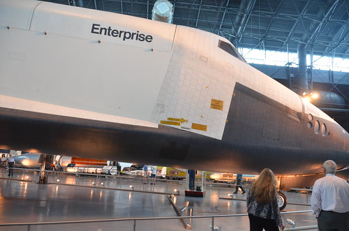
Image by Chris Devers
See more photos of this, and the Wikipedia article.
Details, quoting from Smithsonian National Air and Space Museum | Space Shuttle Enterprise:
Manufacturer:
Rockwell International Corporation
Country of Origin:
United States of America
Dimensions:
Overall: 57 ft. tall x 122 ft. long x 78 ft. wing span, 150,000 lb.
(1737.36 x 3718.57 x 2377.44cm, 68039.6kg)
Materials:
Aluminum airframe and body with some fiberglass features; payload bay doors are graphite epoxy composite; thermal tiles are simulated (polyurethane foam) except for test samples of actual tiles and thermal blankets.
The first Space Shuttle orbiter, "Enterprise," is a full-scale test vehicle used for flights in the atmosphere and tests on the ground; it is not equipped for spaceflight. Although the airframe and flight control elements are like those of the Shuttles flown in space, this vehicle has no propulsion system and only simulated thermal tiles because these features were not needed for atmospheric and ground tests. "Enterprise" was rolled out at Rockwell International’s assembly facility in Palmdale, California, in 1976. In 1977, it entered service for a nine-month-long approach-and-landing test flight program. Thereafter it was used for vibration tests and fit checks at NASA centers, and it also appeared in the 1983 Paris Air Show and the 1984 World’s Fair in New Orleans. In 1985, NASA transferred "Enterprise" to the Smithsonian Institution’s National Air and Space Museum.
Transferred from National Aeronautics and Space Administration
• • •
Quoting from Wikipedia | Space Shuttle Enterprise:
The Space Shuttle Enterprise (NASA Orbiter Vehicle Designation: OV-101) was the first Space Shuttle orbiter. It was built for NASA as part of the Space Shuttle program to perform test flights in the atmosphere. It was constructed without engines or a functional heat shield, and was therefore not capable of spaceflight.
Originally, Enterprise had been intended to be refitted for orbital flight, which would have made it the second space shuttle to fly after Columbia. However, during the construction of Columbia, details of the final design changed, particularly with regard to the weight of the fuselage and wings. Refitting Enterprise for spaceflight would have involved dismantling the orbiter and returning the sections to subcontractors across the country. As this was an expensive proposition, it was determined to be less costly to build Challenger around a body frame (STA-099) that had been created as a test article. Similarly, Enterprise was considered for refit to replace Challenger after the latter was destroyed, but Endeavour was built from structural spares instead.
Service
Construction began on the first orbiter on June 4, 1974. Designated OV-101, it was originally planned to be named Constitution and unveiled on Constitution Day, September 17, 1976. A write-in campaign by Trekkies to President Gerald Ford asked that the orbiter be named after the Starship Enterprise, featured on the television show Star Trek. Although Ford did not mention the campaign, the president—who during World War II had served on the aircraft carrier USS Monterey (CVL-26) that served with USS Enterprise (CV-6)—said that he was "partial to the name" and overrode NASA officials.
The design of OV-101 was not the same as that planned for OV-102, the first flight model; the tail was constructed differently, and it did not have the interfaces to mount OMS pods. A large number of subsystems—ranging from main engines to radar equipment—were not installed on this vehicle, but the capacity to add them in the future was retained. Instead of a thermal protection system, its surface was primarily fiberglass.
In mid-1976, the orbiter was used for ground vibration tests, allowing engineers to compare data from an actual flight vehicle with theoretical models.
On September 17, 1976, Enterprise was rolled out of Rockwell’s plant at Palmdale, California. In recognition of its fictional namesake, Star Trek creator Gene Roddenberry and most of the principal cast of the original series of Star Trek were on hand at the dedication ceremony.
Approach and landing tests (ALT)
Main article: Approach and Landing Tests
On January 31, 1977, it was taken by road to Dryden Flight Research Center at Edwards Air Force Base, to begin operational testing.
While at NASA Dryden, Enterprise was used by NASA for a variety of ground and flight tests intended to validate aspects of the shuttle program. The initial nine-month testing period was referred to by the acronym ALT, for "Approach and Landing Test". These tests included a maiden "flight" on February 18, 1977 atop a Boeing 747 Shuttle Carrier Aircraft (SCA) to measure structural loads and ground handling and braking characteristics of the mated system. Ground tests of all orbiter subsystems were carried out to verify functionality prior to atmospheric flight.
The mated Enterprise/SCA combination was then subjected to five test flights with Enterprise unmanned and unactivated. The purpose of these test flights was to measure the flight characteristics of the mated combination. These tests were followed with three test flights with Enterprise manned to test the shuttle flight control systems.
Enterprise underwent five free flights where the craft separated from the SCA and was landed under astronaut control. These tests verified the flight characteristics of the orbiter design and were carried out under several aerodynamic and weight configurations. On the fifth and final glider flight, pilot-induced oscillation problems were revealed, which had to be addressed before the first orbital launch occurred.
On August 12, 1977, the space shuttle Enterprise flew on its own for the first time.
Preparation for STS-1
Following the ALT program, Enterprise was ferried among several NASA facilities to configure the craft for vibration testing. In June 1979, it was mated with an external tank and solid rocket boosters (known as a boilerplate configuration) and tested in a launch configuration at Kennedy Space Center Launch Pad 39A.
Retirement
With the completion of critical testing, Enterprise was partially disassembled to allow certain components to be reused in other shuttles, then underwent an international tour visiting France, Germany, Italy, the United Kingdom, Canada, and the U.S. states of California, Alabama, and Louisiana (during the 1984 Louisiana World Exposition). It was also used to fit-check the never-used shuttle launch pad at Vandenberg AFB, California. Finally, on November 18, 1985, Enterprise was ferried to Washington, D.C., where it became property of the Smithsonian Institution.
Post-Challenger
After the Challenger disaster, NASA considered using Enterprise as a replacement. However refitting the shuttle with all of the necessary equipment needed for it to be used in space was considered, but instead it was decided to use spares constructed at the same time as Discovery and Atlantis to build Endeavour.
Post-Columbia
In 2003, after the breakup of Columbia during re-entry, the Columbia Accident Investigation Board conducted tests at Southwest Research Institute, which used an air gun to shoot foam blocks of similar size, mass and speed to that which struck Columbia at a test structure which mechanically replicated the orbiter wing leading edge. They removed a fiberglass panel from Enterprise’s wing to perform analysis of the material and attached it to the test structure, then shot a foam block at it. While the panel was not broken as a result of the test, the impact was enough to permanently deform a seal. As the reinforced carbon-carbon (RCC) panel on Columbia was 2.5 times weaker, this suggested that the RCC leading edge would have been shattered. Additional tests on the fiberglass were canceled in order not to risk damaging the test apparatus, and a panel from Discovery was tested to determine the effects of the foam on a similarly-aged RCC leading edge. On July 7, 2003, a foam impact test created a hole 41 cm by 42.5 cm (16.1 inches by 16.7 inches) in the protective RCC panel. The tests clearly demonstrated that a foam impact of the type Columbia sustained could seriously breach the protective RCC panels on the wing leading edge.
The board determined that the probable cause of the accident was that the foam impact caused a breach of a reinforced carbon-carbon panel along the leading edge of Columbia’s left wing, allowing hot gases generated during re-entry to enter the wing and cause structural collapse. This caused Columbia to spin out of control, breaking up with the loss of the entire crew.
Museum exhibit
Enterprise was stored at the Smithsonian’s hangar at Washington Dulles International Airport before it was restored and moved to the newly built Smithsonian’s National Air and Space Museum‘s Steven F. Udvar-Hazy Center at Dulles International Airport, where it has been the centerpiece of the space collection. On April 12, 2011, NASA announced that Space Shuttle Discovery, the most traveled orbiter in the fleet, will be added to the collection once the Shuttle fleet is retired. When that happens, Enterprise will be moved to the Intrepid Sea-Air-Space Museum in New York City, to a newly constructed hangar adjacent to the museum. In preparation for the anticipated relocation, engineers evaluated the vehicle in early 2010 and determined that it was safe to fly on the Shuttle Carrier Aircraft once again.
Cool Cnc Turning Machining photos
A handful of good cnc turning machining images I located:
9-axis CNC turning/milling machine
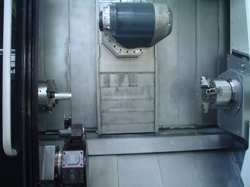
Image by CatarinaMota
CTX gamma 1250 TC gildemeister @ Arts et Métiers – ParisTech
Cool Gear Grinding images
Check out these gear grinding photos:
Image from web page 665 of “Electric railway overview” (1906)
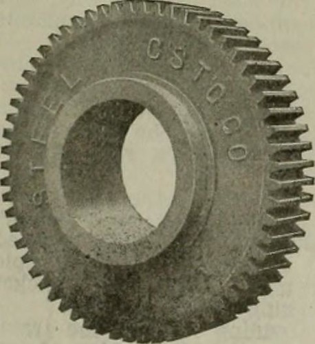
Image by Web Archive Book Images
Identifier: electricrailwayr18amer
Title: Electric railway review
Year: 1906 (1900s)
Authors: American Street and Interurban Railway Association
Subjects: Street-railroads Electric railroads
Publisher: Chicago : Wilson Co
Contributing Library: Carnegie Library of Pittsburgh
Digitizing Sponsor: Lyrasis Members and Sloan Foundation
View Book Web page: Book Viewer
About This Book: Catalog Entry
View All Pictures: All Images From Book
Click right here to view book online to see this illustration in context in a browseable on the internet version of this book.
Text Appearing Just before Image:
Is considerably lighter than the regulartype-C brake of the identical gear ratio of which it is a modifica-tion. The brake has been on the industry less than a month. TITAN GEARS. The material composing the Titan gears manufactured bythe Atha Steel Casting Firm, of Newark, N. J., is so tough that it cannot be reduce by anytool steel however-known. Allfinished surfaces, such asteeth and hub-fit, are ac-curately ground to tem-plates. Despite the fact that the ma-terial is hard, it is notbrittle on the contrary itis so difficult that test pieceshave been bent coldthrough an angle of 180degrees with out showingfracture. The gear is madesolid with the teeth castin, then a special machinegrinds the periphery of theteeth to the correct di-ameter. An additional machinegrinds each and every tooth to themaster, whilst nevertheless one more machine grinds out the hub-match and faces both sides. A gray iron or soft steel hub is thenpressed in at a pressure of 35 to 4.five tons per square inch,and is bored out to the proper size for forcing on the axle.
Text Appearing Right after Image:
Titan Gear. When arrangements have been getting produced for the Louisianapurchase exposition, held in St. Louis, Mo., in 1904, a specialcommittee was appointed to contemplate the question of streetpaving. Soon after an exhaustive investigation Bitulithic wasselected for Lindell boulevard, the primary thoroughfare whichled to the principal entrance to the exposition. The wisdomof this specific committee later was indicated by the superiorjury of awards, which granted to Bitulithic the gold medalas the nearest method to the perfect pavement. The James-town boulevard commission also chosen Bitulithic above allothers for the boulevard to the Jamestown, (Va.), expositiongrounds. A rail bond with a conductivity of two-thirds that of therail is obtained only below exceptional circumstances, but arail bond of such conductivity that the drop of possible acrosstwo feet of bonded rail is significantly less than the drop of potentialacross two feet of strong rail would surely seem to be theideal bond. Harold P. Brown, 120 Libe
Note About Pictures
Please note that these photos are extracted from scanned page pictures that may possibly have been digitally enhanced for readability – coloration and appearance of these illustrations may not perfectly resemble the original function.
Image from page 463 of “Farm machinery and farm motors” (1908)
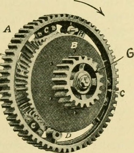
Image by Internet Archive Book Images
Identifier: farmmachineryfar00davi
Title: Farm machinery and farm motors
Year: 1908 (1900s)
Authors: Davidson, Jay Brownlee Chase, Leon Wilson
Subjects: Agricultural machinery
Publisher: New York, O. Judd firm [and so forth., and so on.]
Contributing Library: The Library of Congress
Digitizing Sponsor: Sloan Foundation
View Book Web page: Book Viewer
About This Book: Catalog Entry
View All Pictures: All Images From Book
Click here to view book on-line to see this illustration in context in a browseable on-line version of this book.
Text Appearing Ahead of Image:
turn will propel the drivewheels. But if the drivewheel attached to pinion Ghappens to travel more rapidly thanthat attached to shaft F the^^^^. , pinion C will revolve and ^9^^EB^^^£.^^SJliL ^^^^^ ^^^ pinion A will propel^^^^S»^BSi^rtF«»c the gearing. Usually there are some quite serious jerks onthe transmission gearing ofan engine and some com-panies are now inserting intheir compensating gears aset of springs which take this jar off the gearing. 590. Traction.—Any traction engine has power enoughto propel itself over the road and by way of the fields pro-vided the drive wheels do not slip. Consequently thematter of the wheels adhering to the ground is an im-portant portion. Where the road surface is firm there is nodifficulty but in a soft field excellent problems is experienceddue to the reality that the lugs of the drive wheels tear upthe earth and let the drive wheels to move withoutmoving the engine. It is a widespread belief that the driv^ewheel which has the sharpest lug is the one particular which will
Text Appearing After Image:
FIG- 335—COMPENSATING GEARS 452 FARM MOTORS adhere to the ground the very best. In almost all instances thisis not accurate, given that the lug which is sharp is quite apt to cutthrough the earth, even though one particular which is dull or round anddoes not have such penetrating impact will pack the earthdown and therefore make a lot more resistance for itself whilepassing via the earth. Practically each engine builderhas a style of lug of his personal. Fig. 338 shows a newstyle of traction wheel which seems to be giving verygood results. The far more weight that can be place on tothe drive wheels of an engine the better it will adhereto the ground, offering the surface is firm enough tosupport the load. This makes the matter of location of the principal axles upon theboiler an critical issue.When the boiler is rear-mounted it is obvious thatmore of the weight isthrown upon the frontwheels, which act as aguide, than when thePjg ^,g boiler is side-mounted. Hence one particular would be led tobelieve that the side-mounted traction engine will havebetter
Note About Pictures
Please note that these images are extracted from scanned web page images that could have been digitally enhanced for readability – coloration and appearance of these illustrations may possibly not completely resemble the original function.
Cool Electric Discharge Grinding images
A few good electric discharge grinding images I found:
Lightning Striking Longs Peak Foothills three
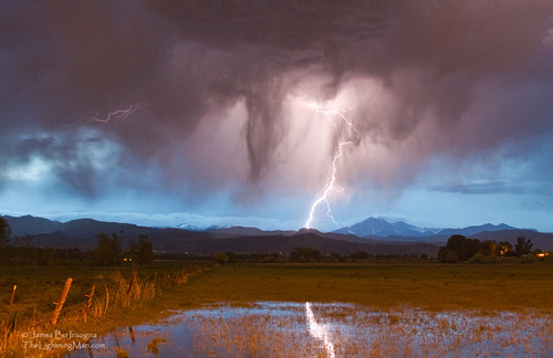
Image by Striking Photography by Bo Insogna
Lightning bolts, cloud to ground striking the front variety foothills of the Colorado Rocky Mountains in Boulder County. A view of the Twin Peaks, Mount Meeker 13,911′ and Longs Peak 14,256′ in the distance. A really uncommon sight to see simply because with most storms the cloud cover is low and you can not see the Peaks or Continental Divide. James Bo Insogna (C) 2012 – All Rights Reserved. 1-888-682-0122
Larger image: www.jamesinsogna.com/Climate/Lightning-Thunderstorm-Weath…
Lightning Chicken?
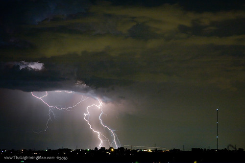
Image by Striking Photography by Bo Insogna
Lightning in the shape of a Man or Chicken with his head in the clouds. What do you see?
Boulder County Colorado.
Acquire Fine art striking nature landscape lightning storm photography prints, posters, greeting cards and stock pictures for licensing. www.TheLightningMan.com 303-834-2524
Let’s Split
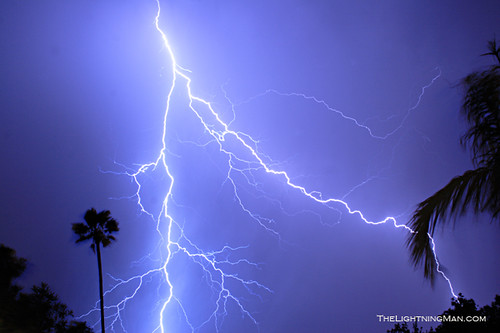
Image by Striking Photography by Bo Insogna
Let’s Split. Lightning Photography image. f10 10 sec exposure.
Cool Grinding Centerless images
A few nice grinding centerless pictures I discovered:
M&S Centerless Grinding, Inc. – Jobs That Spend Tour

Image by governortomwolf
April 27, 2015
Hatboro, PA
M&S Centerless Grinding, Inc. – Jobs That Spend Tour
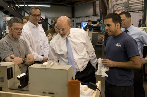
Image by governortomwolf
April 27, 2015
Hatboro, PA
Cool Turning Manufacturing photos
Some cool turning manufacturing photos:
Image from page 49 of “The velvet and corduroy market a short account of the a variety of processes connected with the manufacture of cotton pile goods” (1922)
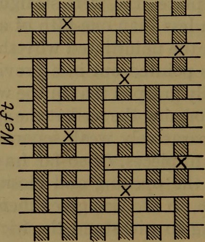
Image by Net Archive Book Photos
Identifier: velvetcorduroyin00cook
Title: The velvet and corduroy sector a brief account of the numerous processes connected with the manufacture of cotton pile goods
Year: 1922 (1920s)
Authors: Cooke, J. Herbert
Subjects: Velvet Cotton manufacture
Publisher: London, New York [and so forth.] Sir I. Pitman & sons, ltd
Contributing Library: Smithsonian Libraries
Digitizing Sponsor: Smithsonian Libraries
View Book Page: Book Viewer
About This Book: Catalog Entry
View All Images: All Images From Book
Click right here to view book online to see this illustration in context in a browseable online version of this book.
Text Appearing Prior to Image:
two,500 and 3,500 instances, it willbe realized that the sizing, to withstand the friction,is a matter for excellent care and experience. A variety of Types. In a plain kind of cloth, in the separa-tion of the warp threads for the passage of the weftbetween, the yarn is equally divided, i.e. just as manythreads are above as below the line of weft, and mechan-ically this is reversed for the next choose or line of weft,but in a velvet, fustian, or any cloth in which the weftis used to kind the face or pile, it is needed that asmuch as possible of the weft shall be laid on the surface,only enough warp threads being introduced to hold 34 VELVET AND CORDUROY Sector the weft and preserve it in its position when reduce, and herewe take advantage of the healds to Hft just as numerous,or as couple of, of the warp threads as may be necessary to holdthe weft, and the mechanism of the loom is adaptedto this end. The manner of varying the sequence in the liftingof the warp threads, and so producing a adjust in the V^arf) or
Text Appearing Following Image:
TwistX Cut right here following weaving. Diagram A PLAIN VELVET pattern and character of the velvet to be woven, willbe dealt with presently, and it will be shown how altera-tions in the lifting of the warp threads make thedifferent qualities of velvet to be described later on. A general concept of the intersection of threads to formthe pattern of a plain velvet is shown in Diagram A. The weft yarn to type the pile is normally made ofthe finest extended staple American cotton, although notinfrequently the good varieties of Egyptian or Soudancotton are used. The good quality have to be of the bestso as to turn out a excellent velvet piece, and to produce PREPARATION—SPINNING AND WEAVING 35 the excellent, soft and complete pile, so characteristicallybeautiful and rich hunting. It is important that theweft used must be spun as soft as feasible, with aslittle binding or handle of the fibres as is practicable,as considering that the pile mentioned is produced up of the ends oflarge numbers of definite and separate fibres, theymust be allo
Note About Photos
Please note that these pictures are extracted from scanned page images that may possibly have been digitally enhanced for readability – coloration and appearance of these illustrations may not perfectly resemble the original function.
Image from page 164 of “Manufacturing possibilities in the state of Washington” (1918)
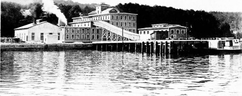
Image by Web Archive Book Photos
Identifier: cu31924003609272
Title: Manufacturing opportunities in the state of Washington
Year: 1918 (1910s)
Authors: Washington (State). Workplace of the Secretary of State. Bureau of Statistics and Immigration
Subjects: Manufactures
Publisher: Olympia, Wash. Public printer
Contributing Library: Cornell University Library
Digitizing Sponsor: MSN
View Book Page: Book Viewer
About This Book: Catalog Entry
View All Pictures: All Photos From Book
Click here to view book on-line to see this illustration in context in a browseable on-line version of this book.
Text Appearing Prior to Image:
itiesof quite high grade limestone, cheap fuel and a tremendous timberwaste from which to get the carbon. Turning to our all-natural supplies of obtainable nitrogen, thecoals of this state include, on an typical, about oneper cent, of their weight in nitrogen. When the coal is heatedto make coke or gas, the greatest element of this nitrogen can be Fcrtiliztr He.soiircfs 161 recovcTud in the kind of aninionium sulpliatc—a -aluahk for-tiliztT niatiTial. The gas functions of our larger cities are now coUeetino- niaiivtons of this nitrogen, but in the eoke ovens in the State ofWashington great quantities of valuable nitrogen components arebeing wasteil. Kventuallv, in this state, as is now being exten-sively (lone in Germany, coal will be distilled for the nitrogenand the useful oils and waxes. Some of oiir coals appear partie-ularlv adapted to this use. FISH WASTE. Washingtons greatest contribution to the nitrogeiiois fer-tilizer su[)plv is in the type of dried and treated fish scrap or
Text Appearing Soon after Image:
eutl-lisli packin.ii plant. fish guano. The greatest component of this guano is supplied byth< whaling businesses. 1 organization was formed for the pur-pose of working up dog fish and other worthless fisli. The Pacific Merchandise Company of Seattle and Port Town-send is functioning up the worthless fish as well as salmon canneryuaste. Appioximately 1,000 tons of ready fish fertilizer istlieii annual output. 3 and si.x-tenths tons raw fish makeone ton fertilizer, this containing about 11 per cent ni-tiogeii and 14 per cent bone phosphate. For years the salmon canneries threw away a trcinendoustonnage of scrap—some 40 or 50 })er cent of the weight of the 16!^ Manufacturing Opportunities in Washington fish—liuads, fins, viscera, and so on. These days, considerably of this scrap issaved and, when appropriately treated, forms a extremely fine fertilizermaterial containing both nitrogen and phosphorus. Processeshave been created whereby it is possible for cannery men topartially remedy their scrap and colle
Note About Images
Please note that these photos are extracted from scanned page images that may have been digitally enhanced for readability – coloration and appearance of these illustrations might not completely resemble the original operate.
Cool Tool Grinding Services images
A handful of nice tool grinding services photos I discovered:
20150827-NRCS-LSC-0449
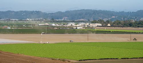
Image by USDAgov
Farming consumers use Pajaro Valley Water Management Agency (PVWMA) water from the City of Watson Water Resources Center (observed in center) that continually produces sanitizes wastewater for use directly or right after blending with ground (properly) water to irrigate the approximately ,000,000 of crops that grow every year, in Watsonville, CA, on Thursday, August 27, 2015.
The Pajaro Valley growers do not use surface water sources from coastal mountain ranges, rivers, aqueducts and reservoirs. Farms and reduce flower growers in this valley pump 98% of agricultural water from underground water sources. There are rivers and streams in the valley, but not for agriculture. In spite of this, and the current crucial drought, agriculture continues to grow, and so does the demands for water.
PVWMA is operating with the Department of the Interior (DOI) U.S. Geological Survey (USGS) to develop a hydrologic model, a tool to aid strategy water management facilities. This has led to the construction of pipelines and water provide facilities that offer a supplement source of water. A single of them is the Recycle Water Facility (center) in the Water Resources Center, adjacent to the Pajaro River.
The Water Resources Center’s very first facility was constructed in the 1920’s to eliminate solids from the neighboring City of Watsonville, and the Town of Pajaro’s wastewater. Pajaro is seen behind and to the left of the Center. In the 1970’s the second phase treatment facility was completed to achieve biological (micro-organisms) and chemical processing that sufficiently treated the water for discharge into the Monterey Bay National Marine Refuge. Considering that the 2009 opening of its third phase, the Water Recycling Facility, a drought-tolerant operation takes in six-million gallons per day from the second phase facility, and produces a disinfected supply of water for high worth agriculture. Here, coagulation, sedimentation and flocculation occurs, followed by filtration and ultraviolet light treatment to sterilize the reclaimed water. Standards are set by California Division of Public Overall health, per Title 22.
It produces roughly 2,000 gallons per minute or 4,000 acre/ft. for the duration of the agricultural year. Reclaimed water customers are educated the water is highly monitored and government tested. Reclaimed water in component or entire is delivered through distribution pipes that are painted an market common purple color, and serves as a public reminder of their efforts.
The procedure sometimes leaves much more salt than particular crops can tolerate. To decrease the percentage, it is blended with ground water or recharge water with lower salt levels to adjust for a crop’s tolerance level, keeping the farms productive and workers employed.
In line with it’s efforts use and produce sustainable and renewable resources, the facility makes use of photovoltaic (solar panels) to produce electrical energy to support offset the power wants of the four 350hp distribution pumps that can move 12,000 gallons per minute out the growers along the 20 mile extended pipeline, who at the end need to have pressurized flows of 300-five,000 gallons per minute. Its 16,000 sq. ft. office developing is LEED Platinum and Net Zero Electricity rated and that exemplifies and supports education of the public by way of guided tours of the facility, exhibits, and center.
Agency was formed in 1984 to address lengthy-term ground water over draught concerns of lowered aquifers, subsidence and saltwater intrusion. Lowered aquifers resulted from much more water getting pumped out of below sea level aquifers than can be refilled. The natural signifies of recharging (refilling) the aquifer comes from rain and other freshwater sources. The water filters down, by way of the ground, to underground spaces that collect in water basins.
A single of the key shoppers of the water is a Harkins Slough Managed Aquifer Recharge and Recovery Facility that pumps winter runoff from a slough (or river channel) to recharge a 45-acre/feet percolation basin (a shallow hilltop lake) exactly where it percolates into the groundwater aquifer. The stored water is either pumped out in the summer season for irrigation, or is kept underground to recharge the aquifer.
Only a couple of miles away, the Pacific Ocean saltwater in Monterey Bay soaks the coastline and exerts a all-natural push into the land. With out enough water in the aquifer to push back the seawater intrusion, salt enters the aquifer. If also salty, the water harms plants alternatively of nourishing them, making it unusable. When seawater enters an aquifer that is beneath sea level, it is not constantly feasible to reverse it, permanently loosing a freshwater aquifer.
The Pajaro Valley Water Management Agency is a state-chartered water management district, and paid for the construction of the Water Recycling Facility, now owned by City of Watsonville. The water it produces belongs to PVWMA.
The agency has a 3-component Base and Management Strategy that focuses on water conservation, optimization of current facilities and new facilities.
In the 30 years PVWMA has been in business their strategy has evolved. By bring in as several public, organization and governmental stakeholders they can hear far more solutions and work in a collaborative style. Some of the stakeholders are USDA Organic Sources Conservation Service (NRCS), DOI USGS, Resource Conservation Districts (RCD) Community Water Dialogue (CWD,) Central Coast Agricultural Water Quality Coalition. Stakeholder aid them attain out and teach efficiencies to agricultural businesses and homeowners.
www.pvwma.dst.ca.us/
www.usgbc.org/leed
www.nrcs.usda.gov/wps/portal/nrcs/website/national/property/
www.usgs.gov/
USDA Photo By Lance Cheung.
20150827-NRCS-LSC-0432

Image by USDAgov
Pajaro Valley Water Management Agency (PVWMA) sanitized wastewater is identified by purple pipes employed provide water to growers who use it as is or in blends with salty ground (properly) water to minimize the salt content for agriculture use, in Watsonville, CA, on Thursday, August 27, 2015.
The Pajaro Valley does not use surface water resources from coastal mountain ranges, rivers, aqueducts and reservoirs. Farms and reduce flower growers in this valley pump 98% of agricultural water from underground water sources. There are rivers and streams in the valley, but not for agriculture.
PVWMA is functioning with the Department of the Interior (DOI) U.S. Geological Survey (USGS) to develop a hydrologic model, a tool to aid plan water management facilities. This has led to the construction of pipelines and water provide facilities that give a supplement source of water. One of them is the Recycle Water Facility in the City of Watsonville Water Sources Center, adjacent to the Pajaro River.
It is the third and most recent phase of the Water Resources Center that was first facility was constructed in the 1920’s that removed the solids from the wastewater. In the 1970’s the second phase and treatment facility was completed to accomplish biological (microorganisms) and chemical processing. Ahead of 2009, water sufficiently treated to be discharged into the Monterey Bay National Marine Refuge. Considering that the 2009 opening of its third phase, Water Recycling Facility, a drought-tolerant operation, requires in 6-million gallons per day from the City of Watsonville, and the Town of Pajaro, and produces a disinfected supply of water for higher value agriculture. Right here, coagulation, sedimentation and flocculation occur in open outdoor tanks, followed by filtration and ultraviolet light treatment sterilizing the reclaimed water. Requirements are set by California Department of Public Well being, per Title 22.
It produces around two,000 gallons per minute or 4,000 acre/ft. during the agricultural year. Reclaimed water customers are educated the water is very monitored and government tested. Reclaimed water in component or complete is delivered by way of distribution pipes that are painted an market normal purple color, and serves as a public reminder of their efforts.
The procedure occasionally leaves a lot more salt far more than specific crops can tolerate. To minimize the percentage, it is blended with ground water or recharge water with lower salt levels to adjust for the plant’s tolerance level and keeps the farms productive and workers employed.
In line with it is efforts use and create sustainable and renewable sources, the facility uses photovoltaic (solar panels) to produce electricity to assist offset the energy demands of the 4 350hp distribution pumps that can move 12,000 gallons per minute out the growers along the 20 mile lengthy pipeline, who at the finish need pressurized flows of 300-five,000 gallons per minute. Its 16,000 sq. ft. office constructing is LEED Platinum and Net Zero Electrical energy rated and that exemplifies and supports education of the public by way of guided tours of the facility, exhibits, and center.
Agency was formed in 1984 to address long-term ground water over draught issues of lowered aquifers, subsidence and saltwater intrusion. Lowered aquifers resulted from more water becoming pumped out of beneath sea level aquifers than can be refilled. The organic indicates of recharging (refilling) the aquifer comes from rain and other freshwater sources. The water filters down, by means of the ground, to underground spaces that gather in water basins.
1 of the key shoppers of the water is a Harkins Slough Managed Aquifer Recharge and Recovery Facility that pumps winter runoff from a slough (or river channel) to recharge a 14-acre percolation basin (a shallow hilltop lake) where it percolates into the groundwater aquifer. The stored water is either pumped out in the summer season for irrigation, or is kept underground to recharge the aquifer.
Only a couple of miles away, the Pacific Ocean saltwater in Monterey Bay soaks the coastline and exerts a natural pushes into the land. With out adequate water in the aquifer to push back the seawater intrusion, salt enters the aquifer. If also salty, the water harms plants as an alternative of nourishing them, creating it unusable. When seawater enters an aquifer that is under sea level, it is not constantly feasible to reverse it, permanently loosing a freshwater aquifer.
The Pajaro Valley Water Management Agency is a state-chartered water management district, and paid for the building of the Water Recycling Facility, now owned by City of Watsonville. The water it produces belongs to PVWMA.
The agency has a three-portion Base and Management Program that focuses on water conservation, optimization of current facilities and new facilities.
In the 30 years PVWMA has been in enterprise their approach has evolved, bringing as numerous public, company and governmental stakeholders in to hear all solutions and operating in a collaborative fashion. Some stakeholders include, USDA Organic Sources Conservation Service (NRCS), DOI USGS, Resource Conservation Districts (RCD) Community Water Dialogue (CWD,) Central Coast Agricultural Water Top quality Coalition to attain out and teach efficiencies to agricultural companies and home owners.
www.pvwma.dst.ca.us/
www.usgbc.org/leed
www.nrcs.usda.gov/wps/portal/nrcs/website/national/property/
www.usgs.gov/
USDA Photo By Lance Cheung.
Cool Cnc Cutting Service images
Some cool cnc cutting service photos:
slab-side pin connection
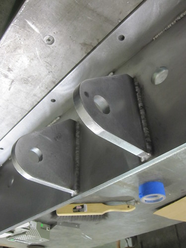
Image by Caliper Studio
Center stringer comfort stair connects two workplace floors in Starret Lehigh creating. Stringer and slab edge assemblies are blackened. Twenty four stainless steel treads are welded to the stringer kind a continuous ribbon. 1 1/four" diameter handrail posts are continuous bent "C" shapes that wrap about treds and are welded to stringer. Stair will be delivered to website in one piece [24′ lengthy 3′ wide 3′ tall @ 2000lbs].
Style by Diller Scofidio + Renfro
Detailing, Fabrication and Installation by Caliper Studio. Caliper Studio engaged Eckersley O’Callaghan & partners for engineering services.
Blackened steel stair with stainless treads
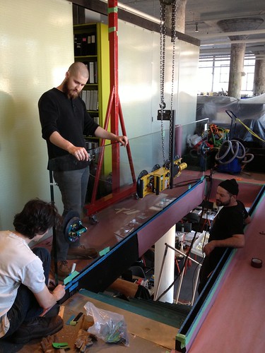
Image by Caliper Studio
Center stringer comfort stair connects two office floors in Starret Lehigh developing. Stringer and slab edge assemblies are blackened. Twenty 4 stainless steel treads are welded to the stringer type a continuous ribbon. 1 1/4" diameter handrail posts are continuous bent "C" shapes that wrap about treds and are welded to stringer. Stair will be delivered to internet site in one particular piece [24′ lengthy 3′ wide 3′ tall @ 2000lbs].
Design by Diller Scofidio + Renfro
Detailing, Fabrication and Installation by Caliper Studio. Caliper Studio engaged Eckersley O’Callaghan & partners for engineering services.
from beneath riser nosing bottom
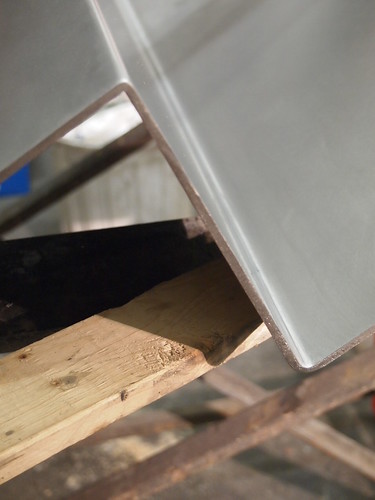
Image by Caliper Studio
Center stringer convenience stair connects two workplace floors in Starret Lehigh developing. Stringer and slab edge assemblies are blackened. Twenty four stainless steel treads are welded to the stringer type a continuous ribbon. 1 1/four" diameter handrail posts are continuous bent "C" shapes that wrap around treds and are welded to stringer. Stair will be delivered to internet site in one particular piece [24′ lengthy 3′ wide 3′ tall @ 2000lbs].
Design and style by Diller Scofidio + Renfro
Detailing, Fabrication and Installation by Caliper Studio. Caliper Studio engaged Eckersley O’Callaghan & partners for engineering solutions.
Cool Milling Turning pictures
A few nice milling turning pictures I discovered:
The Quays, Wicklow, Co. Wicklow
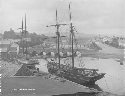
Image by National Library of Ireland on The Commons
To finish this week we turn to matters maritime! The quays in Wicklow as we could only envision them. That wee ship is a good neat vessel and clearly nicely cared for OR brand spanking new?
Niall McAuley Was operating overtime nowadays, he supplied all the needed mapping information and manages to convincingly narrow the date range to between 1905 and 1912.
patrick.vickers1 knows the river here very nicely and tells us "The berth shown is exactly where the an old Brixham schooner utilized to be. Probably much better identified as the Susan Vittery, ex Brooklands. A record holder on the fruit run from the Azores, sunk in a gale in 1953 close to the Tuskar. When the tide was going down my grandfather and other individuals use to rake for mussels on the reduce arches of the river. The scene shown does not appear a lot distinct than seventy years ago !
Photographer: Robert French
Collection: The Lawrence Photograph Collection
Date: between ca.1905 – 1912
NLI Ref: L_ROY_09470
You can also view this image, and several thousands of other folks, on the NLI’s catalogue at catalogue.nli.ie
Kungsparken, Malmö, Sweden
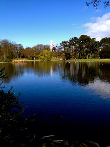
Image by Maria Eklind
Spring 2014