Image from web page 7 of “The Gardeners’ chronicle and agricultural gazette” (1844)

Image from web page 7 of “The Gardeners’ chronicle and agricultural gazette” (1844)

A handful of good id od grinding images I found:

Image from page 7 of “The Gardeners’ chronicle and agricultural gazette” (1844)

Image by World wide web Archive Book Photos
Identifier: gardenerschronic1868lond
Title: The Gardeners’ chronicle and agricultural gazette
Year: 1844 (1840s)
Authors:
Subjects: Gardening Agriculture
Publisher: [London : Published for the proprietors
Contributing Library: UMass Amherst Libraries
Digitizing Sponsor: Boston Library Consortium Member Libraries

View Book Web page: Book Viewer
About This Book: Catalog Entry
View All Images: All Images From Book

Click right here to view book on-line to see this illustration in context in a browseable on the web version of this book.

Text Appearing Prior to Image:
early spnng to October, 1am justified in saying it is a most charming addition to the flowergarden, far more specially for little beds and front lines, for which itI effectively adapted. Like all Violas it requries very good rich soil and plenty of □ &gt, and prefers a moist SUPEEB GLADIOLI, ia 200 Varieties,Selections of Early Varieties for pots or ground, 63., 10s., and15s. per dozen.Selections of RAMOSUS HYBRIDS, 3s., Gs.. and 9s. per dozen. All the above need to be planted without delay.Selections of GANDAVENSIS HYBKIDS, 3«., 6s., i)»., 12*., andl&amps. per dozen. 100 Roots, in ten vartetiea, for 18s. Od. one hundred Roots, 1 100 Roots,one hundred Roots,Decision LILIES, in 70 finest and 2i8. per dozea.HEBBACE6uS and ALPINE PLANTS.-A fine Collection of thet and greatest in cultivation a DESCRIPTIVE CATALOGUE„^tpi ■ ■ ..18s., Basic Nursery Stock. A KCHIBALD HENDER- J. SON begs to inform his triendsand patrons that his DESCRIFflVEand PRICED CATALOGUE ofGENERAL NURSERY SrOCK ispublished, containing sensible

Text Appearing Right after Image:
Decision COLLECTIONS ofVINES in pots ever provided to the A. H.s BULB CATALOGUE contains a Pick List of Kitchen Garden and Flower Seeds for autumn sowing also a Selection Assortment of Gladioli for spnng nlanting. CATALOGUES may be had gratis and post totally free on application. Sion Nursery, Thornton Heath, Surrey, and at the East Surrey Seed Warehouse, College Grounds, North Finish. Ci-oydon. TREES FOREST VC EEDLING O ASH, two-yr., 2s. BEECH, 3-yr., 3s. G(I. HOLLIEai-yr., 5s.OAK. 3-yr , 7s. 6d. Swift, 1-yr., Is. Cd. SILVER FIR. 6-yr.,3s 6d • SPRUCE, six-yr., three#.6d. CRAB. three-yr.. 6s. and SYCAMORE,three-yr., 3s. 6d. per lOOO. Cheaper by the 100.000. Apply to J. RiDDELL, Pai-k Attwood, Bewdley, Worcesterabire. H Larch, Quick, &ampc. AND G. EARNSWOKTH, Nursertien, Matlock, • Derbyshire, have to offer a quantity of LARCH, 3 to 4 feet,and well rooted Strong Rapid, SPRUCE FIR, 9 to 15 inches, Larch, &ampc. LARCH, 2i to 4 feet. Ids. three to four^ feet, 17*. six^.31 to six feet, 20s. SCOTCH FIR, 1 togardenerschronic1868lond

Note About Pictures
Please note that these pictures are extracted from scanned web page images that may have been digitally enhanced for readability – coloration and look of these illustrations may not completely resemble the original perform.

Image from web page 166 of “The marine mammals of the north-western coast of North America, described and illustrated together with an account of the American whale-fishery” (1874)

Image by Internet Archive Book Images
Identifier: marinemammalsofn00scam
Title: The marine mammals of the north-western coast of North America, described and illustrated collectively with an account of the American whale-fishery
Year: 1874 (1870s)
Authors: Scammon, Charles Melville, 1825-1911
Subjects: Marine mammals Cetacea Sealing Whaling Whales Dolphins
Publisher: San Francisco, J.H. Carmany New York, Putnam
Contributing Library: Smithsonian Libraries
Digitizing Sponsor: Smithsonian Libraries

View Book Page: Book Viewer
About This Book: Catalog Entry
View All Photos: All Images From Book

Click here to view book on-line to see this illustration in context in a browseable on the internet version of this book.

Text Appearing Ahead of Image:

Text Appearing Right after Image:
rO O 7^Id en CD^ SI CO &gt g^ O r3 ^ s ■— 1 —- O ^ ^ CO * 1 pi Sm pq S B ■OD OjCO rd V=S 3 &ltu =1CD Ph~- -i five three ■3 § &amp •^ 5 „° o o^ pq fe 5 03 £ –2° I THE DOLPHINS. 101 SECTION VII.—THE Correct WHALE PORPOISE. Ledcorhamphus borealis, Peale. (Plate xix, fig. 3.) The Appropriate Whale Porpoise of the western coast of North America, -in habitand kind, is nearly the identical as the Proper Whale Porpoise of the southern hemi-sphere (Leucorhamphus Peronii), but it is not so beautifully marked, in vivid con-trast, with pure white and jet black, as the latter the former getting black aboveand lighter beneath, with but little of its decrease extremities banded with white. TheLeucorJiamphus borealis is not normally met with in huge numbers, and is seldom foundin shallow bays or lagoons. We have observed them as far south as San Diego Bay,on the California coast, and as far north as Behring Sea showing plainly, that thetwo species of the same genus have a feeding-ground which emb

Note About Pictures
Please note that these photos are extracted from scanned web page pictures that may have been digitally enhanced for readability – coloration and appearance of these illustrations may not completely resemble the original work.


How Keanu Reeves Went From Action Star to Riding Giant

How Keanu Reeves Went From Action Star to Riding Giant
Off the major showroom, which is stocked with sample KRGT-1s, is a mini factory, complete with CAD computer stations, CNC machines that mill modest, precision components from aluminum blocks, and a bone yard of scrapped and forgotten project bikes awaiting&nbsp…
Study more on Maxim

DCC hosts state competition in precision machining
He ended up advancing to fourth location in the nation in his category of CNC turning. This year, he&#39s back in the game — and ready to go farther than ever. Hardy graduated in spring 2015 with an associate degree in precision machining, and he has …
Read more on GoDanRiver.com

Morris Midwest Will Hold an Open House and CNC Machine Tool Show in Maple
Other Tsugami models consist of the compact VA2 Vertical Machining Center, the SS327-5AX 32 mm B-Axis Sliding Headstock Swiss Kind Lathe, the B0206 20 mm 6-Axis Opposed Gang Tool Lathe and SS20M-5AX 20 mm 5-Axis Turn/Mill Multitasking Turning&nbsp…
Read more on PR Internet (press release)

Image from web page 76 of “Kramer’s book of trade secrets for the manufacturer and jobber a total compilation of valuable information and formulae for manufacturing all types of flavoring extracts, baking powders, jellies ..” (1905)

Image from web page 76 of “Kramer’s book of trade secrets for the manufacturer and jobber a total compilation of valuable information and formulae for manufacturing all types of flavoring extracts, baking powders, jellies ..” (1905)

Verify out these machining manufacturer images:

Image from page 76 of “Kramer’s book of trade secrets for the manufacturer and jobber a complete compilation of beneficial data and formulae for manufacturing all types of flavoring extracts, baking powders, jellies ..” (1905)

Image by Web Archive Book Photos
Identifier: kramersbookoftra00kram
Title: Kramer’s book of trade secrets for the manufacturer and jobber a complete compilation of useful details and formulae for manufacturing all sorts of flavoring extracts, baking powders, jellies ..
Year: 1905 (1900s)
Authors: Kramer, Adolph, comp
Subjects: Recipes cbk
Publisher: Sutherland, Ia., Sioux publishing organization
Contributing Library: The Library of Congress
Digitizing Sponsor: Sloan Foundation

View Book Web page: Book Viewer
About This Book: Catalog Entry
View All Photos: All Pictures From Book

Click here to view book on the web to see this illustration in context in a browseable on the internet version of this book.

Text Appearing Before Image:
209-211 S. Clinton St.CHICAGO, ILLINOIS ^AAAAAAAAAAAAAAAAAAAAAAAAAAAAAAAAAAAAAA^ She – We Can Inform Precise Ingredientsof Any Item ^» ^» Do you locate exadly whatyoti want in tnis booR? Do you want to reproduce any specific solution? We analyze anything and can inform the constituents of anycompound or mixture, any ore, metal, alloy, and so on. We treat all inquiries confidentially and furnish absolutelyreliable info, make analysis, assays,-and so forth., at rates thelowest constant with the highest good quality of work. If you want to know the properties of any compound youare preparing to market place it will spend you to seek the advice of us. We employ only chemists who have graduated from repu-table colleges and who have had extended, practical expertise intheir profession. Our laboratories are among the largest andmost entirely equipped of any in the United States and weare ready to give you prompt interest to all inquiries. ^» ^» Max D. Slimmer, PH. D TShe Ellsworth Laboratories Ellsworth Bide., Chicago

Text Appearing Following Image:
A Smsbc VICTOR Provide To any accountable reader of this paperwho will furnish us with references if werequest it, we will ship on Totally free TRIALthe latest model of our Victor RoyalTalking Machine with Unique Exhi-bition Sound Box and your choice of anydozen Victor Records in the catalogue for. Attempt it for a day in your home—if itssatisfactory send us and pay us thebalance .§£A Month For Six Months Unique Notice ^victo^S each and every property in the West, and we will if easyterms will do it. You run no danger, NoC. O. I».or deposit essential. We trust you completely.We ship the machine and records direct to youon completely free trial withoutany conditionswhatever. If it is satisfactory and you make a decision tokeep it, basically spend us as agreed. The Viator Speaking Itf3g&ampt*&amptitt8* is conceded by everyoneIVM*M1rKM&ampSVt&amp tne very best to be had. AtBuffalo and again at St. Louis it was awardedHighest Honors—Gold Medal and 1st prize We guarantee each machine tobe a genuine Victor and the pri

Note About Images
Please note that these images are extracted from scanned web page photos that might have been digitally enhanced for readability – coloration and appearance of these illustrations could not perfectly resemble the original operate.

Steven F. Udvar-Hazy Center: View of south hangar, like B-29 Superfortress “Enola Gay”, a glimpse of the Air France Concorde, and several other folks

Image by Chris Devers
Quoting Smithsonian National Air and Space Museum | Boeing B-29 Superfortress &quotEnola Gay&quot:

Boeing’s B-29 Superfortress was the most sophisticated propeller-driven bomber of World War II and the initial bomber to house its crew in pressurized compartments. Despite the fact that made to fight in the European theater, the B-29 located its niche on the other side of the globe. In the Pacific, B-29s delivered a assortment of aerial weapons: conventional bombs, incendiary bombs, mines, and two nuclear weapons.

On August six, 1945, this Martin-constructed B-29-45-MO dropped the initial atomic weapon used in combat on Hiroshima, Japan. Three days later, Bockscar (on show at the U.S. Air Force Museum close to Dayton, Ohio) dropped a second atomic bomb on Nagasaki, Japan. Enola Gay flew as the advance weather reconnaissance aircraft that day. A third B-29, The Fantastic Artiste, flew as an observation aircraft on both missions.

Transferred from the United States Air Force.

Manufacturer:
Boeing Aircraft Co.
Martin Co., Omaha, Nebr.

Date:
1945

Nation of Origin:
United States of America

Dimensions:
Overall: 900 x 3020cm, 32580kg, 4300cm (29ft 6 5/16in. x 99ft 1in., 71825.9lb., 141ft 15/16in.)

Components:
Polished general aluminum finish

Physical Description:
4-engine heavy bomber with semi-monoqoque fuselage and high-aspect ratio wings. Polished aluminum finish overall, normal late-World War II Army Air Forces insignia on wings and aft fuselage and serial number on vertical fin 509th Composite Group markings painted in black &quotEnola Gay&quot in black, block letters on decrease left nose.

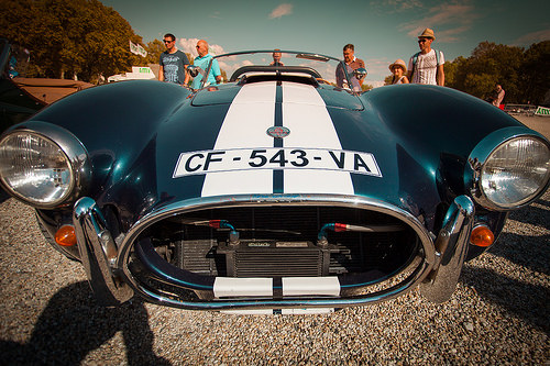
AC Cobra

Image by _ alt3 _
The AC Cobra, sold as the Ford/Shelby AC Cobra in the United States and often known colloquially as the Shelby Cobra in that country, is an American-engined British sports auto produ
ced intermittently given that 1962.

Like numerous British specialist manufacturers, AC Automobiles had been employing the Bristol straight-six engine in its modest-volume production, such as its AC Ace two-seater roadster. This had a hand-constructed physique with a steel tube frame, and aluminium physique panels that had been produced using English wheeling machines. The engine was a pre-Planet War II design and style of BMW which by the 1960s was considered dated. Bristol decided in 1961 to cease production of its engine and instead to use Chrysler 331 cu in (5.4 L) V8 engines. AC began utilizing the 2.6 litre Ford Zephyr engine in its cars. In September 1961, American automotive designer Carroll Shelby wrote to AC asking if they would build him a automobile modified to accept a V8 engine. AC agreed, provided a appropriate engine could be discovered. Shelby went to Chevrolet to see if they would offer him with engines, but not wanting to add competitors to the Corvette they mentioned no. Even so, Ford wanted a vehicle that could compete with the Corvette and they occurred to have a brand new engine which could be employed in this endeavor: Ford’s 260 in HiPo (4.2 L) engine – a new lightweight, thin-wall cast modest-block V8 tuned for high efficiency. Ford offered Shelby with two engines. In January 1962 mechanics at AC Vehicles in Thames Ditton, Surrey fitted the prototype chassis CSX2000 with a 260 ci Ford V8 borrowed from Ford in the UK the 221 ci was by no means sent. Even so, early engineering drawings had been titled &quotAC Ace 3.6&quot. Right after testing and modification, the engine and transmission were removed and the chassis was air-freighted to Shelby in Los Angeles on 2 February 1962. His team fitted it with an engine and transmission in much less than eight hours at Dean Moon’s shop in Santa Fe Springs, California, and started road-testing.

Santa’s 12th Nutcracker Regiment marching to Molotov’s from the Castro

Verify out these precision grinding services pictures:

Santa’s 12th Nutcracker Regiment marching to Molotov’s from the Castro

Image by Steve Rhodes

santaslittlesecretservice.org/2009/11/13/what-is-christma…

For the most current updates

santaslittlesecretservice.org

sanfranciscosantarchy.wordpress.com

santarchy.com

photos from earlier years

www.flickr.com/photos/ari/collections/72157622991070792/

Santa’s 12th Nutcracker Regiment marching to Molotov’s from the Castro

Image by Steve Rhodes

santaslittlesecretservice.org/2009/11/13/what-is-christma…

For the most current updates

santaslittlesecretservice.org

sanfranciscosantarchy.wordpress.com

santarchy.com

images from earlier years

www.flickr.com/photos/ari/collections/72157622991070792/

Santa’s 12th Nutcracker Regiment marching to Molotov’s from the Castro

Image by Steve Rhodes

santaslittlesecretservice.org/2009/11/13/what-is-christma…

For the newest updates

santaslittlesecretservice.org

sanfranciscosantarchy.wordpress.com

santarchy.com

photographs from earlier years

www.flickr.com/photographs/ari/collections/72157622991070792/

Image from page 1003 of “Electric railway journal” (1908)

Verify out these electrical discharge wire cutting pictures:

Image from page 1003 of “Electric railway journal” (1908)

Image by Net Archive Book Pictures
Identifier: electricrailway511918newy
Title: Electric railway journal
Year: 1908 (1900s)
Authors:
Subjects: Electric railroads
Publisher: [New York] McGraw Hill Pub. Co
Contributing Library: Smithsonian Libraries
Digitizing Sponsor: Smithsonian Libraries

View Book Web page: Book Viewer
About This Book: Catalog Entry
View All Pictures: All Photos From Book

Click here to view book online to see this illustration in context in a browseable on the web version of this book.

Text Appearing Prior to Image:
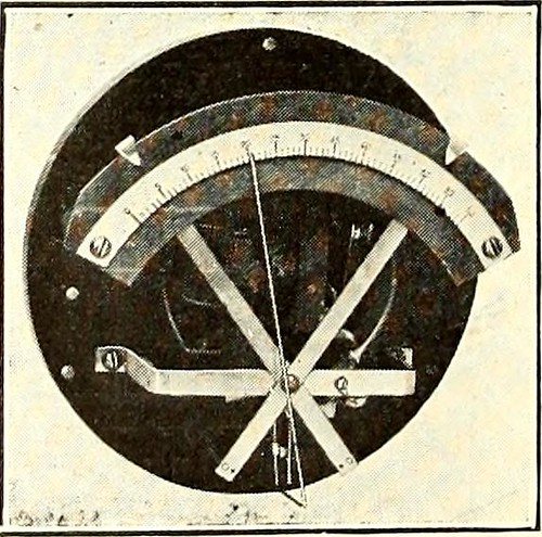
guide inmaking adjustments. The action of the governor is dependent on the Bourdon tube which isconnected to an independ-ent discharge pipe fromthe stress tank. Thefree end of the tube isconnected mechanically tothe indicator needle re-ferred to above. Afterthe governor has been setto the pressure range de-sired, it will automaticallymaintain the stress Pressure GOVERNOR within thoge ,j jt QnWITH CASE REMOVED . * gas or liquid program, thatwill not corrode the Bourdon tube. It can be utilised onboth a.c. and d.c. circuits, and will operate inside set-tings of from 3 to 12 lb. The device is created by the General Electric business,in sizes for rated pressures of 60, one hundred, 160, 300 and500 lb. Governors for higher pressures can also besupplied if desired. Adjustments of the cutting-in andcutting-out pressures are made by moving the pointersshown at the prime of the graduated scale. The case istapped and drilled at the bottom for the pressure pipeand for generating the electrical conduit connections.

Text Appearing After Image:
May 18, 1918 Electric Railway Journal * 975 Trolley Ear Length Is a Factor inWire-Put on Tests Recently Created Show That the Life of theWire Increases Proportionately With theLength of the Ear By G. H. Bolus Designing Engineer, Ohio Brass Organization, Mansfield, Ohio Companies of overhead line material listtrolley ears in all lengths from 7 in. to 15 in.Sales records show that the railway companies of theUnited States and Canada are purchasing a lot more 15-in.ears than those of any other length. The averagerailway man doubtless has standardized on the lengthof ear which he has discovered from knowledge works wellon his line, but it is doubtful whether or not he directly asso-ciates the length of the trolley ear with the put on onthe trolley wire. Some railway properties make a practice of startingtheir installation with a 9-in. ear, operating it untilworn out and replacing with a 12-in. ear to cover upthe worn spots in the wire. The next renewal wouldbe with a 15-in. ear and later renewals would eitherbe m

Note About Photos
Please note that these photos are extracted from scanned page images that could have been digitally enhanced for readability – coloration and appearance of these illustrations may not perfectly resemble the original operate.

Image from web page 372 of “Radiography and radio-therapeutics” (1919)

Image by World wide web Archive Book Pictures
Identifier: radiographyradio001knox
Title: Radiography and radio-therapeutics
Year: 1919 (1910s)
Authors: Knox, Robert, 1868-1928
Subjects: Radiography Radiography Radiotherapy
Publisher: New York : Macmillan
Contributing Library: Francis A. Countway Library of Medicine
Digitizing Sponsor: Open Understanding Commons and Harvard Medical School

View Book Web page: Book Viewer
About This Book: Catalog Entry
View All Photos: All Photos From Book

Click right here to view book on the web to see this illustration in context in a browseable on-line version of this book.

Text Appearing Ahead of Image:
is not possible to recordupon a plate. But radiographs which are taken instantaneously are ofgreat value as confirmatory proof of changes in the organs, and shouldalways be taken to full the examination. The importance of havinga thoroughly trustworthy fluorescentscreen have to be borne in mind.It is also essential that the screenbe smooth on the surface, andkept scrupulously clean. Thelead glass protection ought to alsobe kept well polished, for even atrace of dirt or pencil mark on itssurface may lead to difficulty, theimportance of this point beingreadily understood where finedetail is getting dealt with. It is also of importance tohave the patient completely nonetheless,especially when radiography isemployed, because the slightestmovement throughout the exposuremay ruin the worth of a plate. The screening stand need to be connectedto earth by a wire, in order to steer clear of providing the patient a shock fromthe electrical discharges which are given off from the tube and metal fittingswhen the former gets challenging.

Text Appearing Right after Image:
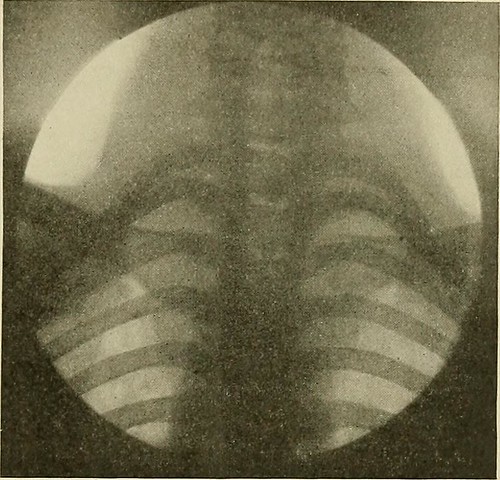
Fig. 247.—Normal reduce cervical and upper dorsalvertebrae. The apical element of both lungs isalso effectively shown. Radiography In radiography of the lungs for diagnostic purposes it is required touse a soft tube in order to obtain the best final results. It is detail in lungs andnot in bone that we appear for. A soft tube of about 3-4 inch spark-gap willallow a massive quantity of current to pass by means of it, and will give extremely gooddetail in the soft parts. Time exposures of any length are of no great worth for diagnosis ifwe are to get plates which will to any extent reproduce what we have seenon the screen, the exposure need to be exceedingly quick in truth, the shortestobtainable is the very best. With a potent modern installation the exposure 284 RADIOGRAPHY could be cut down to T£o of a second. The resulting image is of wonderful worth,because every thing is completely sharp, the heart being represented inoutline by the sharpest possible line. The diaphragm is also sharp, andmay be caught in a stage of

Note About Photos
Please note that these pictures are extracted from scanned web page photos that might have been digitally enhanced for readability – coloration and appearance of these illustrations might not completely resemble the original perform.

Image from page 365 of “Railway mechanical engineer” (1916)

Verify out these internal cylindrical grinding pictures:

Image from web page 365 of “Railway mechanical engineer” (1916)

Image by Net Archive Book Images
Identifier: railwaymechanica96newy
Title: Railway mechanical engineer
Year: 1916 (1910s)
Authors:
Subjects: Railroad engineering Engineering Railroads Railroad vehicles
Publisher: New York, N.Y. : Simmons-Boardman Pub. Co
Contributing Library: Carnegie Library of Pittsburgh
Digitizing Sponsor: Lyrasis Members and Sloan Foundation

View Book Page: Book Viewer
About This Book: Catalog Entry
View All Pictures: All Images From Book

Click right here to view book on the web to see this illustration in context in a browseable on-line version of this book.

Text Appearing Before Image:
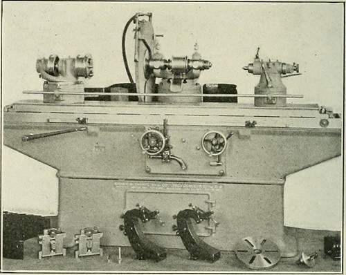
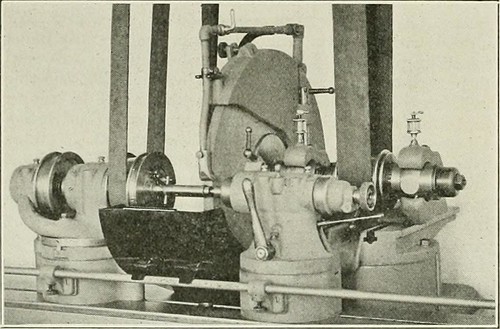
Typlcai Set-Up for Grinding a Little Pin particular throw-blocks adapt this machine for crankshaft perform.The truth that it is a universal machine enables it to do alarge assortment of function, like straight cylindrical grindingand the grinding of abrupt tapers. With the tool rest, it grinds cutters and reamers, boring bars and other tools. Theadvantages this machine possesses over previous models liein the wider range of perform it will cover. With the internal

Text Appearing After Image:
Brown &amp Sharpe Universal and Crankshaft Grinding IVIachlne attachment and tool rest illustrated, it is capable of all thework done by previous models and is also adapted to grind-ing all automotive components except cylinders en bloc. The No. 4 grinder has a capacity to deal with function 60 in. June, 1922 RAILWAY MECHANICAL ENGINEER 353 in length with a swing of 20 J4 in. in diameter and 15 yi in.more than the water guards. The wheel spindle has hardened 4 k Arrangement for Internal Grinding bearings ground and lapped, operating in self-alining phos-phor bronze boxes offered with means of compensation forwear. The automatic cross feed will move the wheel from.00025 to .004 in. at every reversal of the table as preferred. It is automatically disengaged when the operate is to size. Thetable travel is automatic, getting controlled by easily adjust-in a position dogs. The speeds and feeds of the wheel and workand table feed are entirely independent of each and every other. Asingle lever begins and stops the rotation of the operate

Note About Photos
Please note that these pictures are extracted from scanned page photos that may possibly have been digitally enhanced for readability – coloration and appearance of these illustrations may possibly not completely resemble the original perform.

Image from web page 365 of “Railway mechanical engineer” (1916)

Image by Web Archive Book Pictures
Identifier: railwaymechanica96newy
Title: Railway mechanical engineer
Year: 1916 (1910s)
Authors:
Subjects: Railroad engineering Engineering Railroads Railroad cars
Publisher: New York, N.Y. : Simmons-Boardman Pub. Co
Contributing Library: Carnegie Library of Pittsburgh
Digitizing Sponsor: Lyrasis Members and Sloan Foundation

View Book Page: Book Viewer
About This Book: Catalog Entry
View All Photos: All Pictures From Book

Click right here to view book online to see this illustration in context in a browseable on the web version of this book.

Text Appearing Just before Image:
iction clutches, running in oil with manage handles conveniently positioned 1 at the apron and one at thehead finish of the lathe. The clutches call for no adjustmentat any time and are made to pull a tiny a lot more than theload imposed. In addition, these lathes incorporate other Lehmann characteristics, ^■T^ * ■■ I WSSSUmmm 9 r- ^ -^■^•^-^ • J ,•■&gt • M L|gj I^R A ^^w^^g ^fii^^i ^ Lehmann Portable Lathe with Compact Motor Drive Arrangement such as the patent quick adjust mechanism, tailstock spindlelocking device, rod and screw shift, etc., which have beendescribed at different times in the Railway MechanicalEngineer. Universal and Crankshaft Grinding Machine ANEW grinder, recognized as the No. 4 universal andcrankshaft grinding machine, has been created bythe Brown &amp Sharpe Manufacturing Organization, Provi-dence, R. I. It is primarily a universal machine, but adaptedto the grinding of crankshafts. Raising blocks under theheadstock and footstock and a wheel of large diameter, also

Text Appearing After Image:
Typlcai Set-Up for Grinding a Small Pin specific throw-blocks adapt this machine for crankshaft function.The truth that it is a universal machine enables it to do alarge variety of work, including straight cylindrical grindingand the grinding of abrupt tapers. With the tool rest, it grinds cutters and reamers, boring bars and other tools. Theadvantages this machine possesses over previous models liein the wider variety of work it will cover. With the internal

Note About Images
Please note that these images are extracted from scanned web page pictures that may have been digitally enhanced for readability – coloration and appearance of these illustrations could not perfectly resemble the original function.

Image from web page 119 of “American engineer and railroad journal” (1893)

Image by Web Archive Book Images
Identifier: americanengineer79newy
Title: American engineer and railroad journal
Year: 1893 (1890s)
Authors:
Subjects: Railroad engineering Engineering Railroads Railroad automobiles
Publisher: New York : M.N. Forney
Contributing Library: Carnegie Library of Pittsburgh
Digitizing Sponsor: Lyrasis Members and Sloan Foundation

View Book Page: Book Viewer
About This Book: Catalog Entry
View All Pictures: All Pictures From Book

Click here to view book on the web to see this illustration in context in a browseable on-line version of this book.

Text Appearing Ahead of Image:
the shifter. The clutches may be engaged ordisengaged even though the machine Is in motion, thereby allowingperator to drill a hole, remove the drill and substitute atap and tap the hole with no stopping the machine. Thespindle has a swift reverse speed of two to 1. These machines are created in 24, 28, 32, 3ti and 42-in. sizesby the Cincinnati Machine Tool Company of Cincinnati, whomake a st rict i pei ia II j of upright drills. The device consists of a %-in. diameter steel shaft, which isenclosed inside and arranged to revolve inside a steel tubeof 1 in. inside diameter and 40 ins. lengthy. The shaft is sup-ported and provided bearing by bronze bushings pressed into theends of the tube. One end of the shaft carries an emery wheel,which may vary in diameter from 2 ins. upward, according tothe character of the operate essential the other finish carries adriving pulley for a 1 in. belt. The grinder is bolted on the carriage of an ordinary enginelathe, with the axis of the grinding shaft meticulously paralleled

Text Appearing Right after Image:
TirEHMAi Storagi fob Locomotives.—Mr. Druill Halpinssystem of heat storage has been applied to a locomotive boiler of the i hern Railway of England. A cylindrical e tank is placed on top of the boiler, to which it isconnected by indicates of a pipe The r.-eit water, heated to theemperature as thai of the boiler, is passed by means of thisr Below, I he heal ii am taken from the boiler when the engim anding or the afetj valves are Mowing, in this waj a huge supplj of heat is accessible tohelp the boiler when running. In stationary practice a testby Professor Unvvin has shown a coal saving of 19 per cent.with this program. INTERNAL SURFACE GRINDER FOR NARY LATHE. to the center line of the lathe, by implies of the clamp-blockshown in the engraving. The cylinder or tube to be finishedby grinding is set up and centered in the lathe, with a single endin the cnuck and the outer finish supported by a steady rest.The cylinder is rotated gradually by the lathe in one direction of rotation, whilst the emery wheel is

Note About Photos
Please note that these images are extracted from scanned web page pictures that might have been digitally enhanced for readability – coloration and look of these illustrations may not completely resemble the original operate.

Image from page 463 of “Farm machinery and farm motors” (1908)

Some cool gear grinding photos:

Image from web page 463 of “Farm machinery and farm motors” (1908)

Image by Web Archive Book Images
Identifier: farmmachineryfar00davi
Title: Farm machinery and farm motors
Year: 1908 (1900s)
Authors: Davidson, Jay Brownlee Chase, Leon Wilson
Subjects: Agricultural machinery
Publisher: New York, O. Judd firm [etc., etc.]
Contributing Library: The Library of Congress
Digitizing Sponsor: Sloan Foundation

View Book Web page: Book Viewer
About This Book: Catalog Entry
View All Pictures: All Images From Book

Click right here to view book on-line to see this illustration in context in a browseable on the internet version of this book.

Text Appearing Before Image:
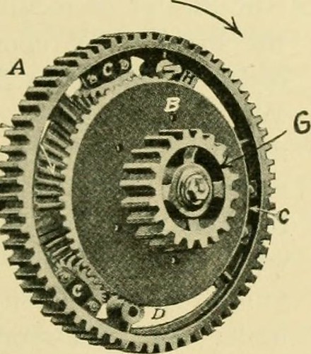
turn will propel the drivewheels. But if the drivewheel attached to pinion Ghappens to travel faster thanthat attached to shaft F the^^^^. , pinion C will revolve and ^9^^EB^^^£.^^SJliL ^^^^^ ^^^ pinion A will propel^^^^S»^BSi^rtF«»c the gearing. Typically there are some quite serious jerks onthe transmission gearing ofan engine and some com-panies are now inserting intheir compensating gears aset of springs which take this jar off the gearing. 590. Traction.—Any traction engine has power enoughto propel itself more than the road and through the fields pro-vided the drive wheels do not slip. Consequently thematter of the wheels adhering to the ground is an im-portant part. Where the road surface is firm there is nodifficulty but in a soft field wonderful difficulty is experienceddue to the fact that the lugs of the drive wheels tear upthe earth and enable the drive wheels to move withoutmoving the engine. It is a typical belief that the driv^ewheel which has the sharpest lug is the a single which will

Text Appearing Soon after Image:
FIG- 335—COMPENSATING GEARS 452 FARM MOTORS adhere to the ground the ideal. In almost all circumstances thisis not true, considering that the lug which is sharp is really apt to cutthrough the earth, while one particular which is dull or round anddoes not have such penetrating impact will pack the earthdown and as a result make far more resistance for itself whilepassing by means of the earth. Nearly each and every engine builderhas a style of lug of his own. Fig. 338 shows a newstyle of traction wheel which seems to be giving verygood final results. The more weight that can be put on tothe drive wheels of an engine the much better it will adhereto the ground, supplying the surface is firm sufficient tosupport the load. This makes the matter of place of the major axles upon theboiler an important element.When the boiler is rear-mounted it is apparent thatmore of the weight isthrown upon the frontwheels, which act as aguide, than when thePjg ^,g boiler is side-mounted. Hence a single would be led tobelieve that the side-mounted traction engine will havebetter

Note About Photos
Please note that these photos are extracted from scanned page photos that could have been digitally enhanced for readability – coloration and appearance of these illustrations could not perfectly resemble the original operate.

Image from page 665 of “Electric railway overview” (1906)

Image by Net Archive Book Photos
Identifier: electricrailwayr18amer
Title: Electric railway review
Year: 1906 (1900s)
Authors: American Street and Interurban Railway Association
Subjects: Street-railroads Electric railroads
Publisher: Chicago : Wilson Co
Contributing Library: Carnegie Library of Pittsburgh
Digitizing Sponsor: Lyrasis Members and Sloan Foundation

View Book Page: Book Viewer
About This Book: Catalog Entry
View All Images: All Pictures From Book

Click right here to view book on-line to see this illustration in context in a browseable on the internet version of this book.

Text Appearing Ahead of Image:
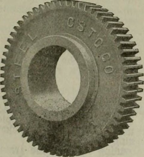
Is considerably lighter than the regulartype-C brake of the same gear ratio of which it is a modifica-tion. The brake has been on the industry significantly less than a month. TITAN GEARS. The material composing the Titan gears manufactured bythe Atha Steel Casting Company, of Newark, N. J., is so difficult that it cannot be reduce by anytool steel yet-recognized. Allfinished surfaces, such asteeth and hub-fit, are ac-curately ground to tem-plates. Although the ma-terial is difficult, it is notbrittle on the contrary itis so hard that test pieceshave been bent coldthrough an angle of 180degrees with no showingfracture. The gear is madesolid with the teeth castin, then a special machinegrinds the periphery of theteeth to the accurate di-ameter. One more machinegrinds every tooth to themaster, while nonetheless one more machine grinds out the hub-match and faces each sides. A gray iron or soft steel hub is thenpressed in at a pressure of 35 to 4.5 tons per square inch,and is bored out to the suitable size for forcing on the axle.

Text Appearing Right after Image:
Titan Gear. When arrangements were becoming made for the Louisianapurchase exposition, held in St. Louis, Mo., in 1904, a specialcommittee was appointed to think about the query of streetpaving. Soon after an exhaustive investigation Bitulithic wasselected for Lindell boulevard, the main thoroughfare whichled to the principal entrance to the exposition. The wisdomof this special committee later was indicated by the superiorjury of awards, which granted to Bitulithic the gold medalas the nearest approach to the best pavement. The James-town boulevard commission also chosen Bitulithic above allothers for the boulevard to the Jamestown, (Va.), expositiongrounds. A rail bond with a conductivity of two-thirds that of therail is obtained only beneath exceptional circumstances, but arail bond of such conductivity that the drop of prospective acrosstwo feet of bonded rail is less than the drop of potentialacross two feet of solid rail would undoubtedly appear to be theideal bond. Harold P. Brown, 120 Libe

Note About Images
Please note that these photos are extracted from scanned web page pictures that may possibly have been digitally enhanced for readability – coloration and appearance of these illustrations might not perfectly resemble the original function.

Image from web page 104 of “Electrical news and engineering” (1891)

Verify out these electrical discharge grinding images:

Image from page 104 of “Electrical news and engineering” (1891)

Image by World wide web Archive Book Pictures
Identifier: electricalnewsen27donm
Title: Electrical news and engineering
Year: 1891 (1890s)
Authors:
Subjects: Electrical engineering
Publisher: Don Mills, Ont. [and so forth.] Southam-Maclean Publications
Contributing Library: Engineering – University of Toronto
Digitizing Sponsor: University of Toronto

View Book Web page: Book Viewer
About This Book: Catalog Entry
View All Photos: All Pictures From Book

Click here to view book online to see this illustration in context in a browseable on the web version of this book.

Text Appearing Prior to Image:
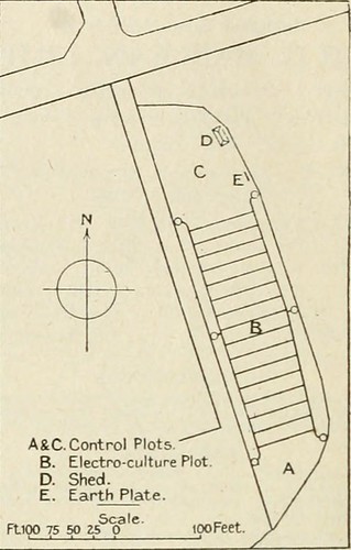
se) King Ed-ward, 1.231 lb. (153 and 117 per cent, increase) Summit. 1.45111). (7.5 increase three.1 per cent, decrease). With regard to the Summits grown on Plot C, it shouldbe noted that the provide wire from the shed to the dischargewire was passed over this ground, at a height of 8 ft. Other vegetables had been grown, but, owing to late planting,no try was produced to get comparative result. Peas,beans, white turnips, swedes, and beet did properly carrots andonions have been very poor, both in top quality and quantity. Greens did nicely, and it was noticeable that these under electroculturewere not attacked Ijy caterpillar to the very same extent as thoseunder all-natural manage. No manure or fertilizer was utilized. The electrical equipment consisted of a ten in. coil, withmercury break-current interrupter and Lodge valves, housedin a wooden shed, 25 yards from the plot, and an earth plateclose to the plot. No. 30 s.w.g. galvanized steel wires wereused for the discharge, placed 15 ft. apart and hooked to 7/16

Text Appearing Right after Image:
A&ampC. Handle Plots B. Electro-culture Plot D. Shed. E. Earth Plate. ScaleFtK) 75 50 ZS one hundred Feet. Fg. 1—Plan of Ground Employed in. s.w.g. span wire attached to insulators, and the whole sup-ported by six poles. To each of the poles was fixed a wrought-iron bar, which enabled the discharge wire to be placed at anydistance from the ground among two ft. 6 in and six ft. six in.The apparatus was supplied with five amperes at 310 volts d.c,wliich would preserve a spark 54 in. long, when an earth wirewas placed that distance from any element of the discharge net-perform. At the commencement the discharge wire was placed asnear as possible to the ground, and, as the crop grew, raised Hours71- six- 5 ■ n L four- 3- J n If n r 1 ■ r nJ r u ^1 Fig. 2—Diagram showing hours per day discharge used to about six in. above the foliage. hen climate and other con-ditions allowed, the discharge was utilised from 6 a.m. to 8 a.m.and 6 p.m. to eight p.m. everyday, and during dull days in between mid-day and 2 p.m. In all the

Note About Photos
Please note that these photos are extracted from scanned web page photos that may have been digitally enhanced for readability – coloration and look of these illustrations could not perfectly resemble the original work.
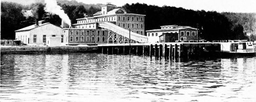
Image from web page 373 of “Journal of electricity, energy, and gas” (1899)

Image by Web Archive Book Images
Identifier: journalofele241251910paci
Title: Journal of electrical energy, power, and gas
Year: 1899 (1890s)
Authors: Pacific Coast Electric Transmission Association
Subjects: Electrical engineering Electricity Gas manufacture and works
Publisher: San Francisco : Technical Pub. Co.
Contributing Library: San Francisco Public Library
Digitizing Sponsor: California State Library Califa/LSTA Grant

View Book Page: Book Viewer
About This Book: Catalog Entry
View All Images: All Pictures From Book

Click here to view book on the web to see this illustration in context in a browseable on the internet version of this book.

Text Appearing Just before Image:
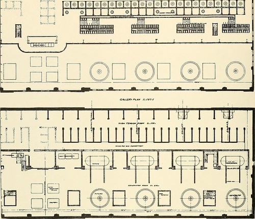
ween the energy-houseand the header. The pipe-lines, like the gate and butterfly valves,are 5 ft. inside diameter. They are sheet steel, weldedon the longitudinal seam, and vary in thickness from13/32 in. at the top to 43/64 in. at the reduce finish, was made in Philadelphia, the latter was riveted to-gether on the ground. The pipe-lines are supportedat intervals by concrete carried nicely down into thebedrock. The typical length is 700 ft. The Energy-House. The web site where the energy-home stands was orig-inally a steep mountainside, but was selected as itofifered a excellent strong rock foundation. A coffer-damwas erected, extending into the river to facilitate ex-cavation, which was carried down till all possibilityof any broken surface rock would be eliminated. Thebuilding is 183 ft. 4 in. lengthy and 71 ft. six in. wide. The foundations are of solid concrete under theheavy machinery, but the rear of the creating is sup- 324 ^.A A i! JOURNAL OF Electricity, Energy AND GAS [Vol. XXIV-No. 15 T I I ri: m

Text Appearing Soon after Image:
ra^ft^i. 00^ Fi.A/v ^t (T ported on concrete columns and arches, the whole con-stituting a piece of perform calculated to stand for alltime. The heavy concrete function is carried up to themain floor. The structure below the primary floor isdivided longitudinally by a heavy supporting wall andthe front also consists of such a wall. The penstocksand primary water-wheels are carried straight on the con-crete foundation, the draft-tubes passing down throughit and discharging under the front wall. The step-bearings and auxiliaries are carried on an arch floor,which is supported amongst the front and longitudinalwalls, and by transverse walls, although the generatorswhich are on the principal floor are also carried on archessimilarly supported. The creating above the major floor has a steelframe with reinforced concrete walls, which supporta steel truss reinforced concrete slab roof. It is dividedinto two longitudinal bays by a series of steel columns.A 50-ton, electrically-operated traveling crane forhandling

Note About Pictures
Please note that these pictures are extracted from scanned page photos that might have been digitally enhanced for readability – coloration and look of these illustrations could not completely resemble the original perform.

Image from web page 118 of “Electrical news and engineering” (1891)

Image by Net Archive Book Images
Identifier: electricalnewsen27donm
Title: Electrical news and engineering
Year: 1891 (1890s)
Authors:
Subjects: Electrical engineering
Publisher: Don Mills, Ont. [etc.] Southam-Maclean Publications
Contributing Library: Engineering – University of Toronto
Digitizing Sponsor: University of Toronto

View Book Page: Book Viewer
About This Book: Catalog Entry
View All Images: All Pictures From Book

Click here to view book on-line to see this illustration in context in a browseable online version of this book.

Text Appearing Ahead of Image:
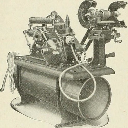
th plug, all mounted on a metal base to forma compact unit, which needs but 48 x 20 inches floor space.T!ie lieight more than all is 40 inches. The air compressor is theair-cooled, two-stage type. The low stress cylinder is three x3 inches in size and the higher stress cylinder is IJ^ x 3inches. The operating stress is 300 pounds per square inch,and the capacity of the compressor is four cubic feet per minute.The compressor operates at 250 to 300 r.p.ni. It is providedwith an intake silencer, which muffles tlie intake noise andtends to force air into the intake valve. When the air in themain tank is raised to the appropriate stress the automaticswitch stops the motor and operates the automatic pressurerelease, which opens beginning tank to the atmosphere. Whenthe automatic switch again begins the motor it also closes thepressure release, and the compressor starts pumping againstno pressure. It always begins with no strain. When the airin the starting tank attains a pressure slightly in excess of

Text Appearing Soon after Image:
that in the primary tank (requiring about ten seconds) it opensthe check valve and charges this tank till the appropriate pres-sure is reached, when the operations are repeated. A trap isprovided in the starting tank, which extracts any moisture oroil that could be discharged from the compressor, assuringpure, dry air, cost-free from oil. The buffing and grinding head issuitable for wheels of 8-inch diameter. The outfit is equippedwith a a single horse-power Robbins &amp Myers motor, which per-mits the compressor and buffing head to operate at the sametime. Outfits with no this buffing head are equipped witli aone-lialf horse-energy R &amp M motor. New Flood-Lighting Projector for Regular Mazda C LampsA new flood-lighting projector, made for use of 300to 1,000-watt common Mazda C lainps, has been placedon the industry by the George Cutter Organization, South Bend,Ind. It is named the Standard Flood-Lighting Projector.The new unit has the identical common construction features asthe Cutter Universal project

Note About Images
Please note that these images are extracted from scanned page photos that could have been digitally enhanced for readability – coloration and look of these illustrations may possibly not perfectly resemble the original operate.