Some cool precision grinding images:
Precision Ground Parts
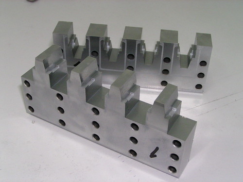
Image by NVT Technologies Pte Ltd
Precision Ground Components
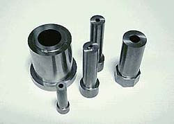
Image by NVT Technologies Pte Ltd
Aluminium Machining China
Some cool precision grinding images:
Precision Ground Parts

Image by NVT Technologies Pte Ltd
Precision Ground Components

Image by NVT Technologies Pte Ltd
New report examines the global cylindrical grinding machine consumption for 2016
Secondly, the report states the international Cylindrical Grinding Machine market size (volume and worth), and the segment markets by regions, sorts, applications and businesses are also discussed. Third, the Cylindrical Grinding Machine market evaluation is …
Study much more on WhaTech
Shop Transitions to Aerospace Function with CNC Grinder
Jon Labrie, general manager J&E Precision Tool Inc., says the Studer S33 universal cylindrical grinder from United Grinding helped the business “take it to the next level” in offering high-precision items. J&E produces a assortment of higher-precision …
Read far more on Contemporary Machine Shop
A handful of good grinding stainless steel pictures I located:
FuJin RaiJin Fighter.Reverse side. Created by Glenn Waters. SOLD. More than eight,000 views of this photo.
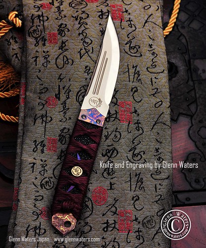
Image by Glenn Waters ぐれんin Japan.
This it the very first knife I have produced in over five years.
After my motor bike accident I couldn’t make knives for some years and then progressively lost the want to make them.
Now I am back and inspired. This is the 1st of many.
About the knife. The blade material is an exotic stainless steel by Hitachi. It is a san mai (Sandwich) of ATS-34 on the outside and ZDP-189 on the inside.
First I ground and shaped the blade soon after which I engraved it with the God of Wind "FuJin" on the front and the God of Thunder "RaiJin" on the back.
Then the blade was heat treated to a RC 67 hardness for the inner steel. Next the blade was polished untill 60,000 grit diamond. Very fine "Micro Mirror Polish.
Right after that I inlaid 24k gold and heat coloured it.
Then black sting ray skin was attached and bound with silk.
The bolsters are created from Titanium Damascus (Timascus). The menuki (handle inserts) are produced of titanium and 18k gold and engraved with bonji (buddhist script) on the front.
Ultimately I took this photo with a Nikon D700 and the superb Nikkor 85mm f/1.4G lens.
Korean War Memorial
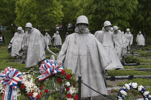
Image by StarrGazr
From 1950 to 1953, the United States joined with the United Nations forces in Korea to take a stand against what was deemed a threat to democratic nations worldwide. At war’s finish, a million and a half American veterans returned to a peacetime world of households, houses, and jobs – and to a country long reluctant to view the Korean War as one thing to memorialize. But to the guys and females who served, the Korean War could in no way be a forgotten war.
The passing of much more than 4 decades has brought a new point of view to the war and its aftermath. The time has come, in the eyes of the Nation, to set aside a location of remembrance for the people who served in this difficult-fought war half a world away. The Korean War Veterans Memorial honors these Americans who answered the contact, these who worked and fought beneath the most trying circumstances, and these who gave their lives for the lead to of freedom.
A War Half a Globe Away
Only 5 years had passed given that the end of World War II when the United States when once more found itself embroiled in a key international conflict. In the early morning hours of June 25, 1950, the communist government of North Korea launched an attack into South Korea. Determined to help the world’s imperiled democracies, the United States quickly sent troops from Japan to join these already stationed in Korea they fought with other nations under the U.N. flag. What was envisioned as a brief, decisive campaign became a prolonged, bitter, frustrating fight that threatened to explode beyond Korean borders. For 3 years the fighting raged. In 1953 an uneasy peace returned by implies of a negotiated settlement that established a new boundary close to the original a single at the 38th parallel.
One-and-a-half million American guys and girls, a correct cross-section of the Nation’s populace, struggled side by side in the course of the conflict. They served as soldiers, chaplains, nurses, clerks, and in a host of other combat and support roles. Several risked their lives in extraordinary acts of heroism. Of these, 131 received the Congressional Medal of Honor, the Nation’s most esteemed tribute for combat bravery.
A Spot for Reflection
Viewed from above, the memorial is a circle interesected by a triangle. Visitors approaching the memorial come 1st to the triangular Field of Service. Here, a group of 19 stainless-steel statues, developed by Globe War II veteran Frank Gaylord, depicts a squad on patrol and evokes the expertise of American ground troops in Korea. Strips of granite and scrubby juniper bushes recommend the rugged Korean terrain, even though windblown ponchos recall the harsh weather. This symbolic patrol brings together members of the U.S. Air Force, Army, Marines, and Navy the men portrayed are from a assortment of ethnic backgrounds.
A granite curb on the north side of the statues lists the 22 nations of the United Nations that sent troops or gave medical assistance in defense of South Korea. On the south side is a black granite wall. Its polished surface mirrors the statues, intermingling the reflected photos with the faces etched into the granite. The etched mural is primarily based on actual photographs of unidentified American soldiers, sailors, airmen, and marines. The faces represent all these who supplied assistance for the ground troops. With each other these pictures reflect the determination of U.S. forces and the numerous ways in which Americans answered their country’s contact to duty.
The adjacent Pool of Remembrance, encircled by a grove of trees, gives a quiet setting. Numbers of those killed, wounded, missing in action, and held prisoner-of-war are etched in stone nearby. Opposite this counting of the war’s toll one more granite wall bears a message inlaid in silver:
Freedom Is Not Cost-free.
Establishment and Dedication
On October 28, 1986, Congress authorized the American Battle Monuments Commission to establish a memorial in Washington, D.C., to honor members of the U.S. armed forces who served in the Korean War. The Korean War Veterans Memorial Advisory Board was appointed by President Ronald Reagan to advocate a website and design and style, and to raise building funds. Ground was broken in November 1993. Frank Gaylord was chosen as the principal sculptor of the statues and Louis Nelson was selected to develop the mural of etched faces on the wall. On July 27, 1995, the 42nd anniversary of the armistice that ended the Korean War, the memorial was committed by President William J. Clinton and Kim Young Sam, President of the Republic of Korea.
Visiting the Memorial
The memorial is staffed from 8 a.m. to midnight each and every day of the year except December 25 by park rangers who are obtainable to answer questions and give talks. A bookstore in the nearby Lincoln Memorial sells informational items relating to each the memorial and the Korean War.
The Korean War Veterans Memorial is element of the National Park Technique, one particular of a lot more than 370 parks representing our nation’s all-natural and cultural heritage. Address inqueries to: Superintendent, National Capital Parks-Central, 900 Ohio Drive, SW, Washington, DC 20024-2000.
Check out these grinding service images:
Waynesburg Pennsylvania ~ The Jackson Hotel ~ Reused Department of Humans Service
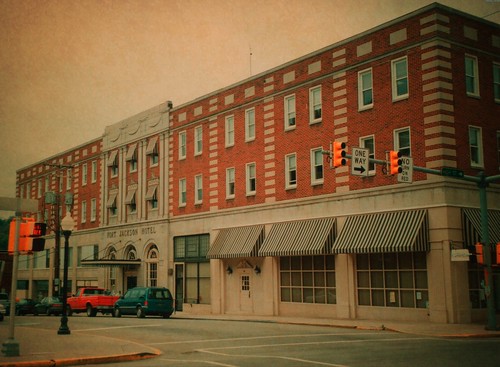
Image by Onasill ~ Bill Badzo
The Fort Jackson Hotel Developing was initially built in 1926, resulting from the tragic Downey Property fire in Dec, 1925 replacing the destroyed 3-story brick Downey Property, directly across from the courthouse. The building was developed by the Pittsburgh architectural firm of Bartholomew & Smith. Building contract was awarded to Baker & Coombs of Morgantown, WV. With steel beams arriving in the summer season and building continuing throught the fall and winter, and int eh the spring of 1927. It quickly became an impressive and attractive addition to downtown Waynesburg. Constructed of red brick and trimmed with Indiana limestone. The hotel lobby was constraucted in the Italian Renaissance style with a higher-beamed ceiling. On the mezzanien floor was a main dining room seating a hundred. As effectively there was a private dining roon that seated 40. The seventy-space hotel had thirty-5 rooms on each of the second and third floors, served by two elevators. The 60-x 180-foot structure housed seven neighborhood businesses on its ground floor (three on Higher Street and 4 on Washington Street). The initial organizations integrated the Ullom & Baily Drugstore, the Fort Jackson barber Shop and the H.C. Schreiber Jewelry Retailer. (Source: The History of Greene County by G. Wayne Smith, Part VI, pg. 865-866)
Soon after a number of years, the developing was acquired by the county and converted into workplace space housing many county workers inside the Division of Human Services
BUCORVUS
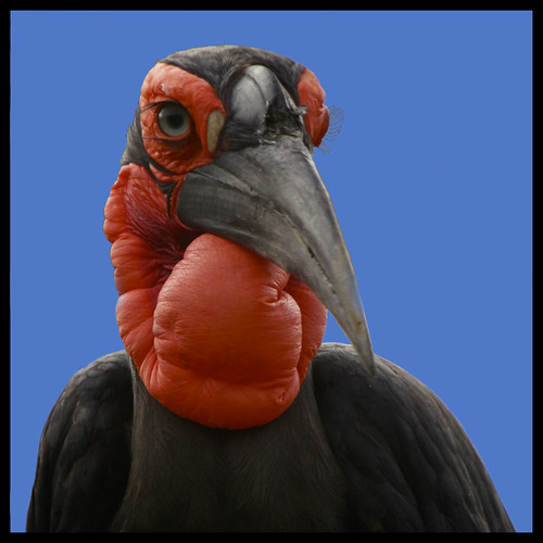
Image by fabiogis50 disgusted but back!!!
Bucorvus cafer
www.parcogallorose.it/index.htm
.
.
.
PhotoAwardsCounter
Click right here to see the awards count for this photo. (?)
pria punya selera
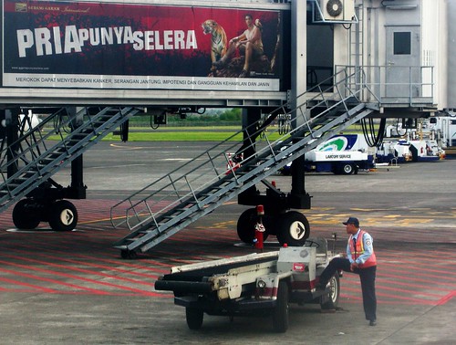
Image by nadi0
Denpasar Airport, Bali.
Check out these surface grinding manufacturer pictures:
Steven F. Udvar-Hazy Center: Vought F4U-1D Corsair
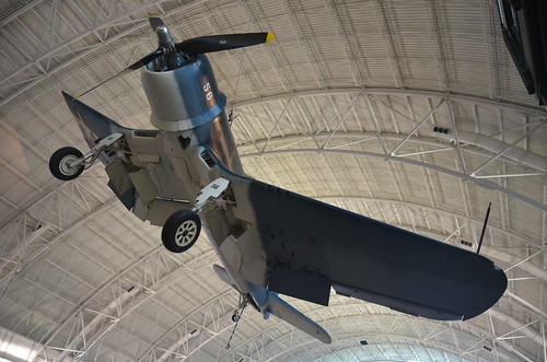
Image by Chris Devers
See more images of this, and the Wikipedia post.
Specifics, quoting from Smithsonian National Air and Space Museum | Vought F4U-1D Corsair:
By V-J Day, September two, 1945, Corsair pilots had amassed an 11:1 kill ratio against enemy aircraft. The aircraft’s distinctive inverted gull-wing design permitted ground clearance for the huge, three-bladed Hamilton Regular Hydromatic propeller, which spanned much more than four meters (13 feet). The Pratt and Whitney R-2800 radial engine and Hydromatic propeller was the largest and one particular of the most strong engine-propeller combinations ever flown on a fighter aircraft.
Charles Lindbergh flew bombing missions in a Corsair with Marine Air Group 31 against Japanese strongholds in the Pacific in 1944. This airplane is painted in the colors and markings of the Corsair Sun Setter, a Marine close-assistance fighter assigned to the USS Essex in July 1944.
Transferred from the United States Navy.
Manufacturer:
Vought Aircraft Business
Date:
1940
Country of Origin:
United States of America
Dimensions:
Overall: 460 x 1020cm, 4037kg, 1250cm (15ft 1 1/8in. x 33ft 5 9/16in., 8900lb., 41ft 1/8in.)
Supplies:
All metal with fabric-covered wings behind the main spar.
Physical Description:
R-2800 radial air-cooled engine with 1,850 horsepower, turned a three-blade Hamilton Normal Hydromatic propeller with solid aluminum blades spanning 13 feet 1 inch wing bent gull-shaped on both sides of the fuselage.
Long Description:
On February 1, 1938, the United States Navy Bureau of Aeronautics requested proposals from American aircraft manufacturers for a new carrier-primarily based fighter airplane. During April, the Vought Aircraft Corporation responded with two styles and one of them, powered by a Pratt & Whitney R-2800 engine, won the competition in June. Significantly less than a year later, Vought test pilot Lyman A. Bullard, Jr., 1st flew the Vought XF4U-1 prototype on Could 29, 1940. At that time, the largest engine driving the greatest propeller ever flown on a fighter aircraft propelled Bullard on this test flight. The R-2800 radial air-cooled engine developed 1,850 horsepower and it turned a 3-blade Hamilton Normal Hydromatic propeller with strong aluminum blades spanning 13 feet 1 inch.
The airplane Bullard flew also had one more striking function, a wing bent gull-shaped on both sides of the fuselage. This arrangement gave further ground clearance for the propeller and lowered drag at the wing-to-fuselage joint. Ironically for a 644-kph (400 mph) airplane, Vought covered the wing with fabric behind the main spar, a practice the organization also followed on the OS2U Kingfisher (see NASM collection).
When naval air strategists had crafted the specifications for the new fighter, the want for speed had overridden all other overall performance goals. With this in thoughts, the Bureau of Aeronautics selected the most strong air-cooled engine offered, the R-2800. Vought assembled a team, lead by chief designer Rex Biesel, to design the very best airframe about this powerful engine. The group included project engineer Frank Albright, aerodynamics engineer Paul Baker, and propulsion engineer James Shoemaker. Biesel and his group succeeded in building a really fast fighter but when they redesigned the prototype for production, they were forced to make an unfortunate compromise.
The Navy requested heavier armament for production Corsairs and Biesel redesigned every outboard folding wing panel to carry three .50 caliber machine guns. These guns displaced fuel tanks installed in each and every wing top edge. To replace this lost capacity, an 897-liter (237 gal) fuselage tank was installed in between the cockpit and the engine. To maintain the speedy and narrow fuselage profile, Biesel could not stack the cockpit on top of the tank, so he moved it almost 3 feet aft. Now the wing fully blocked the pilot’s line of sight throughout the most critical stages of landing. The early Corsair also had a vicious stall, potent torque and propeller effects at slow speed, a quick tail wheel strut, primary gear struts that frequently bounced the airplane at touchdown, and cowl flap actuators that leaked oil onto the windshield. These issues, combined with the lack of cockpit visibility, made the airplane almost not possible to land on the tiny deck of an aircraft carrier. Navy pilots quickly nicknamed the F4U the ‘ensign eliminator’ for its tendency to kill these inexperienced aviators. The Navy refused to clear the F4U for carrier operations until late in 1944, far more than seven years soon after the project started.
This flaw did not deter the Navy from accepting Corsairs because Navy and Marine pilots sorely necessary an improved fighter to replace the Grumman F4F Wildcat (see NASM collection). By New Year’s Eve, 1942, the service owned 178 F4U-1 airplanes. Early in 1943, the Navy decided to divert all Corsairs to land-based United States Marine Corps squadrons and fill Navy carrier-primarily based units with the Grumman F6F Hellcat (see NASM collection). At its ideal speed of 612 kph (380 mph) at six,992 m (23,000 ft), the Hellcat was about 24 kph (15 mph) slower than the Corsair but it was a joy to fly aboard the carrier. The F6F filled in splendidly until improvements to the F4U qualified it for carrier operations. Meanwhile, the Marines on Guadalcanal took their Corsairs into combat and engaged the enemy for the very first time on February 14, 1943, six months just before Hellcat pilots on that battle-scared island initial encountered enemy aircraft.
The F4U had an instant impact on the Pacific air war. Pilots could use the Corsair’s speed and firepower to engage the more maneuverable Japanese airplanes only when the advantage favored the Americans. Unprotected by armor or self-sealing fuel tanks, no Japanese fighter or bomber could withstand for far more than a few seconds the concentrated volley from the six .50 caliber machine guns carried by a Corsair. Key Gregory "Pappy" Boyington assumed command of Marine Corsair squadron VMF-214, nicknamed the ‘Black Sheep’ squadron, on September 7, 1943. Throughout much less than five months of action, Boyington received credit for downing 28 enemy aircraft. Enemy aircraft shot him down on January three, 1944, but he survived the war in a Japanese prison camp.
In Could and June 1944, Charles A. Lindbergh flew Corsair missions with Marine pilots at Green Island and Emirau. On September three, 1944, Lindbergh demonstrated the F4U’s bomb hauling capacity by flying a Corsair from Marine Air Group 31 carrying three bombs each weighing 450 kg (1,000 lb). He dropped this load on enemy positions at Wotje Atoll. On the September eight, Lindbergh dropped the 1st 900-kg (2,000 lb) bomb throughout an attack on the atoll. For the finale 5 days later, the Atlantic flyer delivered a 900-kg (2,000 lb) bomb and two 450-kg (1,000 lb) bombs. Lindbergh went ahead and flew these missions following the commander of MAG-31 informed him that if he was forced down and captured, the Japanese would almost undoubtedly execute him.
As of V-J Day, September two, 1945, the Navy credited Corsair pilots with destroying two,140 enemy aircraft in aerial combat. The Navy and Marines lost 189 F4Us in combat and 1,435 Corsairs in non-combat accidents. Beginning on February 13, 1942, Marine and Navy pilots flew 64,051 operational sorties, 54,470 from runways and 9,581 from carrier decks. Throughout the war, the British Royal Navy accepted two,012 Corsairs and the Royal New Zealand Air Force accepted 364. The demand was so great that the Goodyear Aircraft Corporation and the Brewster Aeronautical Corporation also created the F4U.
Corsairs returned to Navy carrier decks and Marine airfields during the Korean War. On September 10, 1952, Captain Jesse Folmar of Marine Fighter Squadron VMF-312 destroyed a MiG-15 in aerial combat over the west coast of Korea. However, F4U pilots did not have several air-to-air encounters over Korea. Their major mission was to help Allied ground units along the battlefront.
Following the Globe War II, civilian pilots adapted the speedy bent-wing bird from Vought to fly in competitive air races. They preferred modified versions of the F2G-1 and -two originally constructed by Goodyear. Corsairs won the prestigious Thompson Trophy twice. In 1952, Vought manufactured 94 F4U-7s for the French Navy, and these aircraft saw action over Indochina but this order marked the finish of Corsair production. In production longer than any other U.S. fighter to see service in Globe War II, Vought, Goodyear, and Brewster constructed a total of 12,582 F4Us.
The United States Navy donated an F4U-1D to the National Air and Space Museum in September 1960. Vought delivered this Corsair, Bureau of Aeronautics serial number 50375, to the Navy on April 26, 1944. By October, pilots of VF-10 have been flying it but in November, the airplane was transferred to VF-89 at Naval Air Station Atlantic City. It remained there as the squadron moved to NAS Oceana and NAS Norfolk. Throughout February 1945, the Navy withdrew the airplane from active service and transferred it to a pool of surplus aircraft stored at Quantico, Virginia. In 1980, NASM craftsmen restored the F4U-1D in the colors and markings of a Corsair named "Sun Setter," a fighter assigned to Marine Fighter Squadron VMF-114 when that unit served aboard the "USS Essex" in July 1944.
• • •
Quoting from Wikipedia | Vought F4U Corsair:
The Likelihood Vought F4U Corsair was a carrier-capable fighter aircraft that saw service mainly in World War II and the Korean War. Demand for the aircraft soon overwhelmed Vought’s manufacturing capability, resulting in production by Goodyear and Brewster: Goodyear-constructed Corsairs were designated FG and Brewster-built aircraft F3A. From the first prototype delivery to the U.S. Navy in 1940, to final delivery in 1953 to the French, 12,571 F4U Corsairs have been manufactured by Vought, in 16 separate models, in the longest production run of any piston-engined fighter in U.S. history (1942–1953).
The Corsair served in the U.S. Navy, U.S. Marines, Fleet Air Arm and the Royal New Zealand Air Force, as properly as the French Navy Aeronavale and other, smaller, air forces until the 1960s. It speedily became the most capable carrier-primarily based fighter-bomber of World War II. Some Japanese pilots regarded it as the most formidable American fighter of Globe War II, and the U.S. Navy counted an 11:1 kill ratio with the F4U Corsair.
F4U-1D (Corsair Mk IV): Built in parallel with the F4U-1C, but was introduced in April 1944. It had the new -8W water-injection engine. This alter gave the aircraft up to 250 hp (190 kW) much more energy, which, in turn, improved functionality. Speed, for instance, was boosted from 417 miles per hour (671 km/h) to 425 miles per hour (684 km/h). Since of the U.S. Navy’s require for fighter-bombers, it had a payload of rockets double the -1A’s, as nicely as twin-rack plumbing for an further belly drop tank. Such modifications necessitated the need for rocket tabs (attached to fully metal-plated underwing surfaces) and bomb pylons to be bolted on the fighter, however, causing extra drag. Additionally, the role of fighter-bombing was a new activity for the Corsair and the wing fuel cells proved as well vulnerable and had been removed.[] The extra fuel carried by the two drop tanks would nevertheless allow the aircraft to fly relatively extended missions in spite of the heavy, un-aerodynamic load. The normal armament of six machine guns had been implemented as effectively. The canopies of most -1Ds had their struts removed along with their metal caps, which were utilised — at a single point — as a measure to avoid the canopies’ glass from cracking as they moved along the fuselage spines of the fighters.[] Also, the clear-view style "Malcolm Hood" canopy utilized initially on Supermarine Spitfire and P-51C Mustang aircraft was adopted as regular gear for the -1D model, and all later F4U production aircraft. Further production was carried out by Goodyear (FG-1D) and Brewster (F3A-1D). In Fleet Air Arm service, the latter was known as the Corsair III, and each had their wingtips clipped by 8" per wing to let storage in the lower hangars of British carriers.
Customised CNC upgrade simplifies railcar axle grinding
A extensive upgrade of classic high power centreless grinding machine tools is assisting a major railcar axle manufacturer to tremendously simplify precision grinding operations on axle forgings. A important element of the project – which has been managed by …
Study more on Moneycontrol.com
Getting to Know Glebar
Glebar was founded in 1952 by Miner Gleason (the “gle”) and Robert Barhorst (the “bar”) as a manufacturer of centerless plunge-grinding machines. In the 1960s, it adapted its plunge grinding technology to type billiard balls and golf ball cores. (To …
Read far more on Modern day Machine Shop (blog)
Stadler021
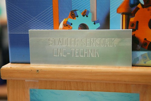
Image by wirtschaftsteiermark
Stadler CNC Technik Detuschfeistritz Steiermark Wirtschaft Buchmann SFG Styria Austria Technologie Innovation technology innovation Metall Verarbeitung
Dieses Bild kann unter Angabe der Quelle verwendet werden
www.wirtschaft.steiermark.at
www.sfg.at
Customised CNC upgrade simplifies railcar axle grinding
A comprehensive upgrade of classic higher energy centreless grinding machine tools is helping a major railcar axle manufacturer to drastically simplify precision grinding operations on axle forgings. A crucial element of the project – which has been managed by …
Study more on Moneycontrol.com
Mastercam integrates Adveon Tool Library
Fair Lawn, New Jersey / Tolland, Connecticut – CNC Software program Inc. and Sandvik Coromant officials have announced that they will be operating with each other to integrate the Adveon Tool Library with Mastercam. Adveon will support Mastercam users to further boost …
Read a lot more on Today’s Health-related Developments
5-Axis Grinder Plus Alternatives Add Up to Significantly A lot more
Recently, Schütte introduced its 325linear machine, a five-axis CNC grinder with extended X- and Y-axis movement, plus two auxiliary slides for workpiece clamping and improved grinding wheel guidance over the whole machining envelope. Micro tools, gun …
Study a lot more on American Machinist
Check out these surface grinding manufacturer images:
Steven F. Udvar-Hazy Center: Space Shuttle Enterprise in the James McDonnell Space Hangar
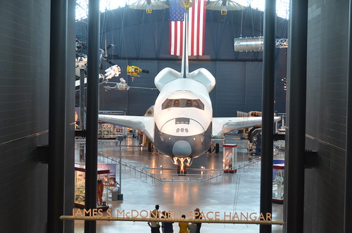
Image by Chris Devers
See more photos of this, and the Wikipedia article.
Details, quoting from Smithsonian National Air and Space Museum | Space Shuttle Enterprise:
Manufacturer:
Rockwell International Corporation
Country of Origin:
United States of America
Dimensions:
Overall: 57 ft. tall x 122 ft. long x 78 ft. wing span, 150,000 lb.
(1737.36 x 3718.57 x 2377.44cm, 68039.6kg)
Materials:
Aluminum airframe and body with some fiberglass features; payload bay doors are graphite epoxy composite; thermal tiles are simulated (polyurethane foam) except for test samples of actual tiles and thermal blankets.
The first Space Shuttle orbiter, "Enterprise," is a full-scale test vehicle used for flights in the atmosphere and tests on the ground; it is not equipped for spaceflight. Although the airframe and flight control elements are like those of the Shuttles flown in space, this vehicle has no propulsion system and only simulated thermal tiles because these features were not needed for atmospheric and ground tests. "Enterprise" was rolled out at Rockwell International’s assembly facility in Palmdale, California, in 1976. In 1977, it entered service for a nine-month-long approach-and-landing test flight program. Thereafter it was used for vibration tests and fit checks at NASA centers, and it also appeared in the 1983 Paris Air Show and the 1984 World’s Fair in New Orleans. In 1985, NASA transferred "Enterprise" to the Smithsonian Institution’s National Air and Space Museum.
Transferred from National Aeronautics and Space Administration
• • •
Quoting from Wikipedia | Space Shuttle Enterprise:
The Space Shuttle Enterprise (NASA Orbiter Vehicle Designation: OV-101) was the first Space Shuttle orbiter. It was built for NASA as part of the Space Shuttle program to perform test flights in the atmosphere. It was constructed without engines or a functional heat shield, and was therefore not capable of spaceflight.
Originally, Enterprise had been intended to be refitted for orbital flight, which would have made it the second space shuttle to fly after Columbia. However, during the construction of Columbia, details of the final design changed, particularly with regard to the weight of the fuselage and wings. Refitting Enterprise for spaceflight would have involved dismantling the orbiter and returning the sections to subcontractors across the country. As this was an expensive proposition, it was determined to be less costly to build Challenger around a body frame (STA-099) that had been created as a test article. Similarly, Enterprise was considered for refit to replace Challenger after the latter was destroyed, but Endeavour was built from structural spares instead.
Service
Construction began on the first orbiter on June 4, 1974. Designated OV-101, it was originally planned to be named Constitution and unveiled on Constitution Day, September 17, 1976. A write-in campaign by Trekkies to President Gerald Ford asked that the orbiter be named after the Starship Enterprise, featured on the television show Star Trek. Although Ford did not mention the campaign, the president—who during World War II had served on the aircraft carrier USS Monterey (CVL-26) that served with USS Enterprise (CV-6)—said that he was "partial to the name" and overrode NASA officials.
The design of OV-101 was not the same as that planned for OV-102, the first flight model; the tail was constructed differently, and it did not have the interfaces to mount OMS pods. A large number of subsystems—ranging from main engines to radar equipment—were not installed on this vehicle, but the capacity to add them in the future was retained. Instead of a thermal protection system, its surface was primarily fiberglass.
In mid-1976, the orbiter was used for ground vibration tests, allowing engineers to compare data from an actual flight vehicle with theoretical models.
On September 17, 1976, Enterprise was rolled out of Rockwell’s plant at Palmdale, California. In recognition of its fictional namesake, Star Trek creator Gene Roddenberry and most of the principal cast of the original series of Star Trek were on hand at the dedication ceremony.
Approach and landing tests (ALT)
Main article: Approach and Landing Tests
On January 31, 1977, it was taken by road to Dryden Flight Research Center at Edwards Air Force Base, to begin operational testing.
While at NASA Dryden, Enterprise was used by NASA for a variety of ground and flight tests intended to validate aspects of the shuttle program. The initial nine-month testing period was referred to by the acronym ALT, for "Approach and Landing Test". These tests included a maiden "flight" on February 18, 1977 atop a Boeing 747 Shuttle Carrier Aircraft (SCA) to measure structural loads and ground handling and braking characteristics of the mated system. Ground tests of all orbiter subsystems were carried out to verify functionality prior to atmospheric flight.
The mated Enterprise/SCA combination was then subjected to five test flights with Enterprise unmanned and unactivated. The purpose of these test flights was to measure the flight characteristics of the mated combination. These tests were followed with three test flights with Enterprise manned to test the shuttle flight control systems.
Enterprise underwent five free flights where the craft separated from the SCA and was landed under astronaut control. These tests verified the flight characteristics of the orbiter design and were carried out under several aerodynamic and weight configurations. On the fifth and final glider flight, pilot-induced oscillation problems were revealed, which had to be addressed before the first orbital launch occurred.
On August 12, 1977, the space shuttle Enterprise flew on its own for the first time.
Preparation for STS-1
Following the ALT program, Enterprise was ferried among several NASA facilities to configure the craft for vibration testing. In June 1979, it was mated with an external tank and solid rocket boosters (known as a boilerplate configuration) and tested in a launch configuration at Kennedy Space Center Launch Pad 39A.
Retirement
With the completion of critical testing, Enterprise was partially disassembled to allow certain components to be reused in other shuttles, then underwent an international tour visiting France, Germany, Italy, the United Kingdom, Canada, and the U.S. states of California, Alabama, and Louisiana (during the 1984 Louisiana World Exposition). It was also used to fit-check the never-used shuttle launch pad at Vandenberg AFB, California. Finally, on November 18, 1985, Enterprise was ferried to Washington, D.C., where it became property of the Smithsonian Institution.
Post-Challenger
After the Challenger disaster, NASA considered using Enterprise as a replacement. However refitting the shuttle with all of the necessary equipment needed for it to be used in space was considered, but instead it was decided to use spares constructed at the same time as Discovery and Atlantis to build Endeavour.
Post-Columbia
In 2003, after the breakup of Columbia during re-entry, the Columbia Accident Investigation Board conducted tests at Southwest Research Institute, which used an air gun to shoot foam blocks of similar size, mass and speed to that which struck Columbia at a test structure which mechanically replicated the orbiter wing leading edge. They removed a fiberglass panel from Enterprise’s wing to perform analysis of the material and attached it to the test structure, then shot a foam block at it. While the panel was not broken as a result of the test, the impact was enough to permanently deform a seal. As the reinforced carbon-carbon (RCC) panel on Columbia was 2.5 times weaker, this suggested that the RCC leading edge would have been shattered. Additional tests on the fiberglass were canceled in order not to risk damaging the test apparatus, and a panel from Discovery was tested to determine the effects of the foam on a similarly-aged RCC leading edge. On July 7, 2003, a foam impact test created a hole 41 cm by 42.5 cm (16.1 inches by 16.7 inches) in the protective RCC panel. The tests clearly demonstrated that a foam impact of the type Columbia sustained could seriously breach the protective RCC panels on the wing leading edge.
The board determined that the probable cause of the accident was that the foam impact caused a breach of a reinforced carbon-carbon panel along the leading edge of Columbia’s left wing, allowing hot gases generated during re-entry to enter the wing and cause structural collapse. This caused Columbia to spin out of control, breaking up with the loss of the entire crew.
Museum exhibit
Enterprise was stored at the Smithsonian’s hangar at Washington Dulles International Airport before it was restored and moved to the newly built Smithsonian’s National Air and Space Museum‘s Steven F. Udvar-Hazy Center at Dulles International Airport, where it has been the centerpiece of the space collection. On April 12, 2011, NASA announced that Space Shuttle Discovery, the most traveled orbiter in the fleet, will be added to the collection once the Shuttle fleet is retired. When that happens, Enterprise will be moved to the Intrepid Sea-Air-Space Museum in New York City, to a newly constructed hangar adjacent to the museum. In preparation for the anticipated relocation, engineers evaluated the vehicle in early 2010 and determined that it was safe to fly on the Shuttle Carrier Aircraft once again.
Steven F. Udvar-Hazy Center: Vought F4U-1D Corsair
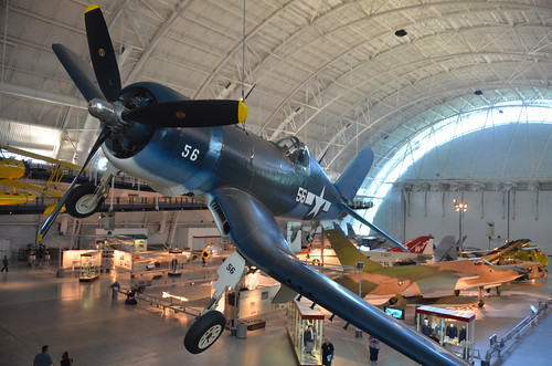
Image by Chris Devers
See more photos of this, and the Wikipedia article.
Details, quoting from Smithsonian National Air and Space Museum | Vought F4U-1D Corsair:
By V-J Day, September 2, 1945, Corsair pilots had amassed an 11:1 kill ratio against enemy aircraft. The aircraft’s distinctive inverted gull-wing design allowed ground clearance for the huge, three-bladed Hamilton Standard Hydromatic propeller, which spanned more than 4 meters (13 feet). The Pratt and Whitney R-2800 radial engine and Hydromatic propeller was the largest and one of the most powerful engine-propeller combinations ever flown on a fighter aircraft.
Charles Lindbergh flew bombing missions in a Corsair with Marine Air Group 31 against Japanese strongholds in the Pacific in 1944. This airplane is painted in the colors and markings of the Corsair Sun Setter, a Marine close-support fighter assigned to the USS Essex in July 1944.
Transferred from the United States Navy.
Manufacturer:
Vought Aircraft Company
Date:
1940
Country of Origin:
United States of America
Dimensions:
Overall: 460 x 1020cm, 4037kg, 1250cm (15ft 1 1/8in. x 33ft 5 9/16in., 8900lb., 41ft 1/8in.)
Materials:
All metal with fabric-covered wings behind the main spar.
Physical Description:
R-2800 radial air-cooled engine with 1,850 horsepower, turned a three-blade Hamilton Standard Hydromatic propeller with solid aluminum blades spanning 13 feet 1 inch; wing bent gull-shaped on both sides of the fuselage.
Long Description:
On February 1, 1938, the United States Navy Bureau of Aeronautics requested proposals from American aircraft manufacturers for a new carrier-based fighter airplane. During April, the Vought Aircraft Corporation responded with two designs and one of them, powered by a Pratt & Whitney R-2800 engine, won the competition in June. Less than a year later, Vought test pilot Lyman A. Bullard, Jr., first flew the Vought XF4U-1 prototype on May 29, 1940. At that time, the largest engine driving the biggest propeller ever flown on a fighter aircraft propelled Bullard on this test flight. The R-2800 radial air-cooled engine developed 1,850 horsepower and it turned a three-blade Hamilton Standard Hydromatic propeller with solid aluminum blades spanning 13 feet 1 inch.
The airplane Bullard flew also had another striking feature, a wing bent gull-shaped on both sides of the fuselage. This arrangement gave additional ground clearance for the propeller and reduced drag at the wing-to-fuselage joint. Ironically for a 644-kph (400 mph) airplane, Vought covered the wing with fabric behind the main spar, a practice the company also followed on the OS2U Kingfisher (see NASM collection).
When naval air strategists had crafted the requirements for the new fighter, the need for speed had overridden all other performance goals. With this in mind, the Bureau of Aeronautics selected the most powerful air-cooled engine available, the R-2800. Vought assembled a team, lead by chief designer Rex Biesel, to design the best airframe around this powerful engine. The group included project engineer Frank Albright, aerodynamics engineer Paul Baker, and propulsion engineer James Shoemaker. Biesel and his team succeeded in building a very fast fighter but when they redesigned the prototype for production, they were forced to make an unfortunate compromise.
The Navy requested heavier armament for production Corsairs and Biesel redesigned each outboard folding wing panel to carry three .50 caliber machine guns. These guns displaced fuel tanks installed in each wing leading edge. To replace this lost capacity, an 897-liter (237 gal) fuselage tank was installed between the cockpit and the engine. To maintain the speedy and narrow fuselage profile, Biesel could not stack the cockpit on top of the tank, so he moved it nearly three feet aft. Now the wing completely blocked the pilot’s line of sight during the most critical stages of landing. The early Corsair also had a vicious stall, powerful torque and propeller effects at slow speed, a short tail wheel strut, main gear struts that often bounced the airplane at touchdown, and cowl flap actuators that leaked oil onto the windshield. These difficulties, combined with the lack of cockpit visibility, made the airplane nearly impossible to land on the tiny deck of an aircraft carrier. Navy pilots soon nicknamed the F4U the ‘ensign eliminator’ for its tendency to kill these inexperienced aviators. The Navy refused to clear the F4U for carrier operations until late in 1944, more than seven years after the project started.
This flaw did not deter the Navy from accepting Corsairs because Navy and Marine pilots sorely needed an improved fighter to replace the Grumman F4F Wildcat (see NASM collection). By New Year’s Eve, 1942, the service owned 178 F4U-1 airplanes. Early in 1943, the Navy decided to divert all Corsairs to land-based United States Marine Corps squadrons and fill Navy carrier-based units with the Grumman F6F Hellcat (see NASM collection). At its best speed of 612 kph (380 mph) at 6,992 m (23,000 ft), the Hellcat was about 24 kph (15 mph) slower than the Corsair but it was a joy to fly aboard the carrier. The F6F filled in splendidly until improvements to the F4U qualified it for carrier operations. Meanwhile, the Marines on Guadalcanal took their Corsairs into combat and engaged the enemy for the first time on February 14, 1943, six months before Hellcat pilots on that battle-scared island first encountered enemy aircraft.
The F4U had an immediate impact on the Pacific air war. Pilots could use the Corsair’s speed and firepower to engage the more maneuverable Japanese airplanes only when the advantage favored the Americans. Unprotected by armor or self-sealing fuel tanks, no Japanese fighter or bomber could withstand for more than a few seconds the concentrated volley from the six .50 caliber machine guns carried by a Corsair. Major Gregory "Pappy" Boyington assumed command of Marine Corsair squadron VMF-214, nicknamed the ‘Black Sheep’ squadron, on September 7, 1943. During less than 5 months of action, Boyington received credit for downing 28 enemy aircraft. Enemy aircraft shot him down on January 3, 1944, but he survived the war in a Japanese prison camp.
In May and June 1944, Charles A. Lindbergh flew Corsair missions with Marine pilots at Green Island and Emirau. On September 3, 1944, Lindbergh demonstrated the F4U’s bomb hauling capacity by flying a Corsair from Marine Air Group 31 carrying three bombs each weighing 450 kg (1,000 lb). He dropped this load on enemy positions at Wotje Atoll. On the September 8, Lindbergh dropped the first 900-kg (2,000 lb) bomb during an attack on the atoll. For the finale five days later, the Atlantic flyer delivered a 900-kg (2,000 lb) bomb and two 450-kg (1,000 lb) bombs. Lindbergh went ahead and flew these missions after the commander of MAG-31 informed him that if he was forced down and captured, the Japanese would almost certainly execute him.
As of V-J Day, September 2, 1945, the Navy credited Corsair pilots with destroying 2,140 enemy aircraft in aerial combat. The Navy and Marines lost 189 F4Us in combat and 1,435 Corsairs in non-combat accidents. Beginning on February 13, 1942, Marine and Navy pilots flew 64,051 operational sorties, 54,470 from runways and 9,581 from carrier decks. During the war, the British Royal Navy accepted 2,012 Corsairs and the Royal New Zealand Air Force accepted 364. The demand was so great that the Goodyear Aircraft Corporation and the Brewster Aeronautical Corporation also produced the F4U.
Corsairs returned to Navy carrier decks and Marine airfields during the Korean War. On September 10, 1952, Captain Jesse Folmar of Marine Fighter Squadron VMF-312 destroyed a MiG-15 in aerial combat over the west coast of Korea. However, F4U pilots did not have many air-to-air encounters over Korea. Their primary mission was to support Allied ground units along the battlefront.
After the World War II, civilian pilots adapted the speedy bent-wing bird from Vought to fly in competitive air races. They preferred modified versions of the F2G-1 and -2 originally built by Goodyear. Corsairs won the prestigious Thompson Trophy twice. In 1952, Vought manufactured 94 F4U-7s for the French Navy, and these aircraft saw action over Indochina but this order marked the end of Corsair production. In production longer than any other U.S. fighter to see service in World War II, Vought, Goodyear, and Brewster built a total of 12,582 F4Us.
The United States Navy donated an F4U-1D to the National Air and Space Museum in September 1960. Vought delivered this Corsair, Bureau of Aeronautics serial number 50375, to the Navy on April 26, 1944. By October, pilots of VF-10 were flying it but in November, the airplane was transferred to VF-89 at Naval Air Station Atlantic City. It remained there as the squadron moved to NAS Oceana and NAS Norfolk. During February 1945, the Navy withdrew the airplane from active service and transferred it to a pool of surplus aircraft stored at Quantico, Virginia. In 1980, NASM craftsmen restored the F4U-1D in the colors and markings of a Corsair named "Sun Setter," a fighter assigned to Marine Fighter Squadron VMF-114 when that unit served aboard the "USS Essex" in July 1944.
• • •
Quoting from Wikipedia | Vought F4U Corsair:
The Chance Vought F4U Corsair was a carrier-capable fighter aircraft that saw service primarily in World War II and the Korean War. Demand for the aircraft soon overwhelmed Vought’s manufacturing capability, resulting in production by Goodyear and Brewster: Goodyear-built Corsairs were designated FG and Brewster-built aircraft F3A. From the first prototype delivery to the U.S. Navy in 1940, to final delivery in 1953 to the French, 12,571 F4U Corsairs were manufactured by Vought, in 16 separate models, in the longest production run of any piston-engined fighter in U.S. history (1942–1953).
The Corsair served in the U.S. Navy, U.S. Marines, Fleet Air Arm and the Royal New Zealand Air Force, as well as the French Navy Aeronavale and other, smaller, air forces until the 1960s. It quickly became the most capable carrier-based fighter-bomber of World War II. Some Japanese pilots regarded it as the most formidable American fighter of World War II, and the U.S. Navy counted an 11:1 kill ratio with the F4U Corsair.
F4U-1D (Corsair Mk IV): Built in parallel with the F4U-1C, but was introduced in April 1944. It had the new -8W water-injection engine. This change gave the aircraft up to 250 hp (190 kW) more power, which, in turn, increased performance. Speed, for example, was boosted from 417 miles per hour (671 km/h) to 425 miles per hour (684 km/h). Because of the U.S. Navy’s need for fighter-bombers, it had a payload of rockets double the -1A’s, as well as twin-rack plumbing for an additional belly drop tank. Such modifications necessitated the need for rocket tabs (attached to fully metal-plated underwing surfaces) and bomb pylons to be bolted on the fighter, however, causing extra drag. Additionally, the role of fighter-bombing was a new task for the Corsair and the wing fuel cells proved too vulnerable and were removed.[] The extra fuel carried by the two drop tanks would still allow the aircraft to fly relatively long missions despite the heavy, un-aerodynamic load. The regular armament of six machine guns were implemented as well. The canopies of most -1Ds had their struts removed along with their metal caps, which were used — at one point — as a measure to prevent the canopies’ glass from cracking as they moved along the fuselage spines of the fighters.[] Also, the clear-view style "Malcolm Hood" canopy used initially on Supermarine Spitfire and P-51C Mustang aircraft was adopted as standard equipment for the -1D model, and all later F4U production aircraft. Additional production was carried out by Goodyear (FG-1D) and Brewster (F3A-1D). In Fleet Air Arm service, the latter was known as the Corsair III, and both had their wingtips clipped by 8" per wing to allow storage in the lower hangars of British carriers.
Steven F. Udvar-Hazy Center: Space Shuttle Enterprise (starboard view)
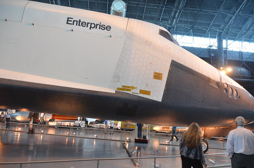
Image by Chris Devers
See more photos of this, and the Wikipedia article.
Details, quoting from Smithsonian National Air and Space Museum | Space Shuttle Enterprise:
Manufacturer:
Rockwell International Corporation
Country of Origin:
United States of America
Dimensions:
Overall: 57 ft. tall x 122 ft. long x 78 ft. wing span, 150,000 lb.
(1737.36 x 3718.57 x 2377.44cm, 68039.6kg)
Materials:
Aluminum airframe and body with some fiberglass features; payload bay doors are graphite epoxy composite; thermal tiles are simulated (polyurethane foam) except for test samples of actual tiles and thermal blankets.
The first Space Shuttle orbiter, "Enterprise," is a full-scale test vehicle used for flights in the atmosphere and tests on the ground; it is not equipped for spaceflight. Although the airframe and flight control elements are like those of the Shuttles flown in space, this vehicle has no propulsion system and only simulated thermal tiles because these features were not needed for atmospheric and ground tests. "Enterprise" was rolled out at Rockwell International’s assembly facility in Palmdale, California, in 1976. In 1977, it entered service for a nine-month-long approach-and-landing test flight program. Thereafter it was used for vibration tests and fit checks at NASA centers, and it also appeared in the 1983 Paris Air Show and the 1984 World’s Fair in New Orleans. In 1985, NASA transferred "Enterprise" to the Smithsonian Institution’s National Air and Space Museum.
Transferred from National Aeronautics and Space Administration
• • •
Quoting from Wikipedia | Space Shuttle Enterprise:
The Space Shuttle Enterprise (NASA Orbiter Vehicle Designation: OV-101) was the first Space Shuttle orbiter. It was built for NASA as part of the Space Shuttle program to perform test flights in the atmosphere. It was constructed without engines or a functional heat shield, and was therefore not capable of spaceflight.
Originally, Enterprise had been intended to be refitted for orbital flight, which would have made it the second space shuttle to fly after Columbia. However, during the construction of Columbia, details of the final design changed, particularly with regard to the weight of the fuselage and wings. Refitting Enterprise for spaceflight would have involved dismantling the orbiter and returning the sections to subcontractors across the country. As this was an expensive proposition, it was determined to be less costly to build Challenger around a body frame (STA-099) that had been created as a test article. Similarly, Enterprise was considered for refit to replace Challenger after the latter was destroyed, but Endeavour was built from structural spares instead.
Service
Construction began on the first orbiter on June 4, 1974. Designated OV-101, it was originally planned to be named Constitution and unveiled on Constitution Day, September 17, 1976. A write-in campaign by Trekkies to President Gerald Ford asked that the orbiter be named after the Starship Enterprise, featured on the television show Star Trek. Although Ford did not mention the campaign, the president—who during World War II had served on the aircraft carrier USS Monterey (CVL-26) that served with USS Enterprise (CV-6)—said that he was "partial to the name" and overrode NASA officials.
The design of OV-101 was not the same as that planned for OV-102, the first flight model; the tail was constructed differently, and it did not have the interfaces to mount OMS pods. A large number of subsystems—ranging from main engines to radar equipment—were not installed on this vehicle, but the capacity to add them in the future was retained. Instead of a thermal protection system, its surface was primarily fiberglass.
In mid-1976, the orbiter was used for ground vibration tests, allowing engineers to compare data from an actual flight vehicle with theoretical models.
On September 17, 1976, Enterprise was rolled out of Rockwell’s plant at Palmdale, California. In recognition of its fictional namesake, Star Trek creator Gene Roddenberry and most of the principal cast of the original series of Star Trek were on hand at the dedication ceremony.
Approach and landing tests (ALT)
Main article: Approach and Landing Tests
On January 31, 1977, it was taken by road to Dryden Flight Research Center at Edwards Air Force Base, to begin operational testing.
While at NASA Dryden, Enterprise was used by NASA for a variety of ground and flight tests intended to validate aspects of the shuttle program. The initial nine-month testing period was referred to by the acronym ALT, for "Approach and Landing Test". These tests included a maiden "flight" on February 18, 1977 atop a Boeing 747 Shuttle Carrier Aircraft (SCA) to measure structural loads and ground handling and braking characteristics of the mated system. Ground tests of all orbiter subsystems were carried out to verify functionality prior to atmospheric flight.
The mated Enterprise/SCA combination was then subjected to five test flights with Enterprise unmanned and unactivated. The purpose of these test flights was to measure the flight characteristics of the mated combination. These tests were followed with three test flights with Enterprise manned to test the shuttle flight control systems.
Enterprise underwent five free flights where the craft separated from the SCA and was landed under astronaut control. These tests verified the flight characteristics of the orbiter design and were carried out under several aerodynamic and weight configurations. On the fifth and final glider flight, pilot-induced oscillation problems were revealed, which had to be addressed before the first orbital launch occurred.
On August 12, 1977, the space shuttle Enterprise flew on its own for the first time.
Preparation for STS-1
Following the ALT program, Enterprise was ferried among several NASA facilities to configure the craft for vibration testing. In June 1979, it was mated with an external tank and solid rocket boosters (known as a boilerplate configuration) and tested in a launch configuration at Kennedy Space Center Launch Pad 39A.
Retirement
With the completion of critical testing, Enterprise was partially disassembled to allow certain components to be reused in other shuttles, then underwent an international tour visiting France, Germany, Italy, the United Kingdom, Canada, and the U.S. states of California, Alabama, and Louisiana (during the 1984 Louisiana World Exposition). It was also used to fit-check the never-used shuttle launch pad at Vandenberg AFB, California. Finally, on November 18, 1985, Enterprise was ferried to Washington, D.C., where it became property of the Smithsonian Institution.
Post-Challenger
After the Challenger disaster, NASA considered using Enterprise as a replacement. However refitting the shuttle with all of the necessary equipment needed for it to be used in space was considered, but instead it was decided to use spares constructed at the same time as Discovery and Atlantis to build Endeavour.
Post-Columbia
In 2003, after the breakup of Columbia during re-entry, the Columbia Accident Investigation Board conducted tests at Southwest Research Institute, which used an air gun to shoot foam blocks of similar size, mass and speed to that which struck Columbia at a test structure which mechanically replicated the orbiter wing leading edge. They removed a fiberglass panel from Enterprise’s wing to perform analysis of the material and attached it to the test structure, then shot a foam block at it. While the panel was not broken as a result of the test, the impact was enough to permanently deform a seal. As the reinforced carbon-carbon (RCC) panel on Columbia was 2.5 times weaker, this suggested that the RCC leading edge would have been shattered. Additional tests on the fiberglass were canceled in order not to risk damaging the test apparatus, and a panel from Discovery was tested to determine the effects of the foam on a similarly-aged RCC leading edge. On July 7, 2003, a foam impact test created a hole 41 cm by 42.5 cm (16.1 inches by 16.7 inches) in the protective RCC panel. The tests clearly demonstrated that a foam impact of the type Columbia sustained could seriously breach the protective RCC panels on the wing leading edge.
The board determined that the probable cause of the accident was that the foam impact caused a breach of a reinforced carbon-carbon panel along the leading edge of Columbia’s left wing, allowing hot gases generated during re-entry to enter the wing and cause structural collapse. This caused Columbia to spin out of control, breaking up with the loss of the entire crew.
Museum exhibit
Enterprise was stored at the Smithsonian’s hangar at Washington Dulles International Airport before it was restored and moved to the newly built Smithsonian’s National Air and Space Museum‘s Steven F. Udvar-Hazy Center at Dulles International Airport, where it has been the centerpiece of the space collection. On April 12, 2011, NASA announced that Space Shuttle Discovery, the most traveled orbiter in the fleet, will be added to the collection once the Shuttle fleet is retired. When that happens, Enterprise will be moved to the Intrepid Sea-Air-Space Museum in New York City, to a newly constructed hangar adjacent to the museum. In preparation for the anticipated relocation, engineers evaluated the vehicle in early 2010 and determined that it was safe to fly on the Shuttle Carrier Aircraft once again.
Array
Obtaining to Know Glebar
Glebar was founded in 1952 by Miner Gleason (the “gle”) and Robert Barhorst (the “bar”) as a manufacturer of centerless plunge-grinding machines. In the 1960s, it adapted its plunge grinding technologies to form billiard balls and golf ball cores. (To …
Read much more on Modern Machine Shop (blog)
Magic Commence Extremely Important Five-Game Road Trip
Skiles is the ultimate “one game at a time'' type of coach, but he also sees great worth in taking specific segments of the season and grouping them collectively for rallying points throughout the 82-game grind. For instance, Skiles not too long ago took to calling the …
Study a lot more on OrlandoMagic.com