Image from page 1215 of “Electric railway journal” (1908)

Image from page 1215 of “Electric railway journal” (1908)

Some cool wire cutting services photos:

Image from page 1215 of “Electric railway journal” (1908)

Image by Web Archive Book Photos
Identifier: electricrailway491917newy
Title: Electric railway journal
Year: 1908 (1900s)
Authors:
Subjects: Electric railroads
Publisher: [New York] McGraw Hill Pub. Co
Contributing Library: Smithsonian Libraries
Digitizing Sponsor: Smithsonian Libraries

View Book Page: Book Viewer
About This Book: Catalog Entry
View All Images: All Images From Book

Click here to view book on the web to see this illustration in context in a browseable on-line version of this book.

Text Appearing Before Image:
COUNTY RAILWAY REMODELED Vehicle The interior of the automobile was improved by substitutinglongitudinal seat frames constructed up of angle-iron for theold wood-inclosed frames, with reduction in fire threat.The new arrangement is also much more sanitary, as it iseasier to hold the floor clean. On the side of the vesti-bule opposite to the door a seat for two persons wasbuilt in, and on the door side a folding seat was placed,permitting complete utilization of the vestibule when thedoor is not in use. All of the seats were covered withrattan. With a wish to have a completely sanitary automobile, all ofthe old grooved and reduce moldings were removed andreplaced with plain ones. Incidentally this significantly im-proved the look. Rico sanitary strap hangers,push buttons and buzzers, Consolidated auto heaters andAtchley staffless brakes have been among the devices whichwe added to make the car as worthy of the name safetycar as attainable. Railings were erected on the platformsto separate the operator from the passengers and also

Text Appearing Soon after Image:
LEVIS COUNTY RAILWAY Auto Just before AND Soon after REMODELING 1192 ELECTRIC RAILWAY JOURNAL [Vol. XLIX, No. 26 to serve as a support for the fare boxes. Two verticalrailing posts have been carried clear to the ceiling to serveas guides for the curtains offered to defend the oper-ator from the light behind him. The new arrangementof lamps consists of seven single ones down the centerof the vehicle, 1 in every vestibule, and Golden Glow head-lights, 1 operating at a time. Safety car lightingfixtures have been used throughout. All of the wiring wasinclosed in versatile or pipe conduits. Lastly the carwas offered an desirable interior finish in mahogany,with cream-enameled ceiling and railings. The remodeled cars are in operation along the southshore of the St. Lawrence River opposite Quebec. Theyconnect with the Quebec ferry service, which is on a

Note About Images
Please note that these photos are extracted from scanned page images that might have been digitally enhanced for readability – coloration and appearance of these illustrations may possibly not completely resemble the original work.

Image from web page 392 of “Canadian engineer” (1893)
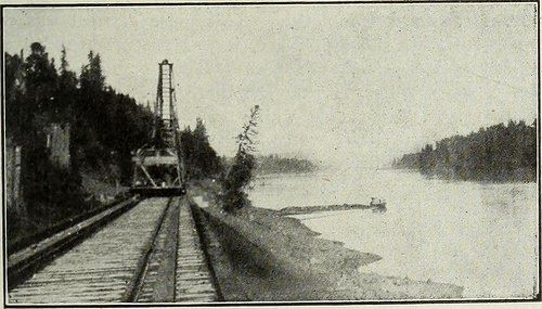
Image by Net Archive Book Pictures
Identifier: canadianengineer22toro
Title: Canadian engineer
Year: 1893 (1890s)
Authors:
Subjects:
Publisher: Toronto, Monetary Instances Print. Co. [and so forth.]
Contributing Library: Engineering – University of Toronto
Digitizing Sponsor: University of Toronto

View Book Web page: Book Viewer
About This Book: Catalog Entry
View All Pictures: All Images From Book

Click right here to view book online to see this illustration in context in a browseable on the web version of this book.

Text Appearing Just before Image:
f alternatebents did not fall opposite to a single yet another. The joists have been of dimensions four in. by ten in., beingstaggered and overlapping one particular foot. They were toe-spikedto the cap with six in. wire spikes. The flooring was three in.in thickness. It ought to have been specified as dressed to3 in. thickness, but this was not done, and in consequencethe very first portion of the floor laid was somewhat rough. Thewharf floor was faced with two pieces of 12 in. by 12 in.wealing drift bolted to one particular an additional, as shown in the eleva-tion, and drifted in turn to the caps. This waling was per-fectly lined, and has provided the face of the wharf a veryfinished appearance, and has also completed great service inoperating the wharf to date. Outside of every of the outer bearing piles were drivenspringing piles of fir. These springing piles were drivenrather farther from the bearing piles than is shown on theplan, getting distant three ft. centres at the river bed, and buttedagainst th? u-in. by 14-in. cap with twelve inches clear be-

Text Appearing Soon after Image:
Fraser River, from C.N.P. Railway Track. tween the piles at the leading. Their object is, of course, totake the shock of a vessel coming to her mooring alongsidethe wharf. These springing piles were cut ofT on a bevel,being flush with the upper 12-in. by 12-in. wale on the in-side, and sloping outward at an inclination of 30 to thehorizontal. This uniformity of slope of these outer pilesconsiderably enhances the appearance of the wharft .A.n 8-in.by 12-in. spacing wale was created quick along the whole faceof the wharf, in between these springing piles. Mooring piles had been driven as shown on the- jjlan. 1 ri&lt ywere braced tD the 4 nearest bearjng piles by means of8-in. by 8-in. struts. On the freight wharf two runways were constructed ac-cording to the specifics shown on the plan. Sliding stringerssupport the removal planks of the flooring more than the run-way, so that when not in use the runways might be coveredin. These sliding stringers operate on rollers suspendedfrom the joists of the adjoini

Note About Images
Please note that these images are extracted from scanned web page images that may possibly have been digitally enhanced for readability – coloration and look of these illustrations may not completely resemble the original work.

Image from page 194 of “North Carolina Christian advocate [serial]” (1894)

Image by Web Archive Book Pictures
Identifier: northcarolinachr49unit
Title: North Carolina Christian advocate [serial]
Year: 1894 (1890s)
Authors: United Methodist Church (U.S.). North Carolina Conference United Methodist Church (U.S.). Western North Carolina Conference
Subjects: United Methodist Church (U.S.). North Carolina Conference United Methodist Church (U.S.). Western North Carolina Conference Methodist Church
Publisher: Greensboro, N.C., Methodist Board of Publication, [and so forth.]
Contributing Library: Duke Divinity School Library, Duke University
Digitizing Sponsor: Institute of Museum and Library Services, beneath the provisions of the Library Services and Technologies Act, administered by the State Library of North Carolina. Grant issued to Duke University for the Religion in North Carolina project.

View Book Page: Book Viewer
About This Book: Catalog Entry
View All Pictures: All Images From Book

Click here to view book on-line to see this illustration in context in a browseable on the internet version of this book.

Text Appearing Prior to Image:
. Her nose and lip wereraw as beef, with offensive dischargefrom the consuming sore. Physicians ad-vised cutting, but it failed. BloodBalm healed the sores, and Mrs.Guerney is as well as ever. BotanicBlood Balm also cures eczema, itch-ing humors, scabs and scales, bonepains, ulcers, offensive pimples,blood poison, carbuncles, scrofula,risings and bumps on the skin andall blood troubles. Druggists, perlarge bottle. Sample of BotanicBlood Balm cost-free and prepaid bywriting Blood Balm Co., Atlanta,Ga. Describe trouble and specialmedical guidance sent in sealed letter.It is surely worth even though investi-gating such a exceptional remedy asBlood Balm cures the moRt awful,worst and most deep seated blood dis-eases. It Saved His Leg. P. A. Danforth of LaGrange, Ga.,suffered for six months with a fright-ful operating sore on his leg but writesthat Bucklens Arnica Salve whollycured it in 5 days. For Ulcers,Wounds, Piles, its the ideal salve inthe world. Remedy assured. Only25cts. Sold by all druggist.

Text Appearing Right after Image:
WomensShoes Created by SouthernGirls and Boys The equal of any .50 shoe on the industry TAKE NOOTHER Your dealer need to hold the ideal,and the best is ROXIE WARD. GEO. D. WITT SHOE GO. Manufacturers LYNCHBURG, VA. |Wire Railing and Ornamental [ ^WIRE Works./?jiD U F U R CEL CO. No. 311N. Howard St., Baltimore, Md. Manufacture wire railing for cemeter-ies, balconies, &ampc seives, fenders,cages, sand and eoa) screens, wovenwire, and so forth keo Iron bedsteads.chair*««tt.e«s. &amp»* C. W. BANNER, M D. OPPOSITE THE MCADOO House. Practice limited to theEye, Ear, Noseand Throat. OFEICE HOURS .—9 a. n&gt. to 1 p. m. 2:30 p.m.to five p. m. Sunday 9 to ten:30 a m. given«^ thP worthv tinnr. 1p three-tf THOMAS C. HOYLB. N. L. EURE. HOYLE &ltSL EURE, Attorneys at Law, 119 COURT SQUARE,GREENSBORO, N.O, Special focus given to collections.Loam negotiated. iftnH-1* Mental Strain Impacted Gen-eral Overall health. Medical doctors Doses Weak-ened Stomach. Dr. Miles Nervine CuredMe. Dr. Miles Restorative Nervine brings r

Note About Images
Please note that these images are extracted from scanned page photos that may have been digitally enhanced for readability – coloration and appearance of these illustrations might not completely resemble the original work.
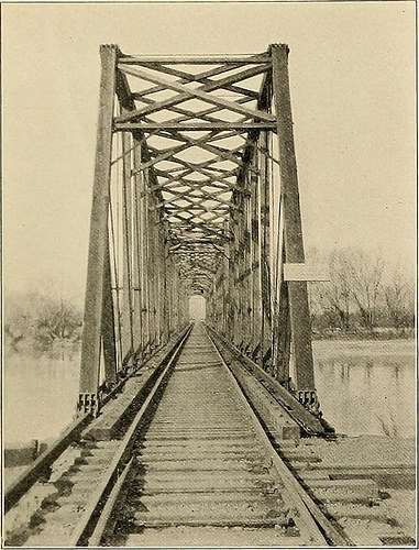
Image from web page 430 of “Journal of electricity, energy, and gas” (1899)

Image from web page 430 of “Journal of electricity, energy, and gas” (1899)

Verify out these turning manufacturing photos:

Image from web page 430 of “Journal of electricity, energy, and gas” (1899)

Image by World wide web Archive Book Pictures
Identifier: journalofele241251910paci
Title: Journal of electrical energy, power, and gas
Year: 1899 (1890s)
Authors: Pacific Coast Electric Transmission Association
Subjects: Electrical engineering Electricity Gas manufacture and performs
Publisher: San Francisco : Technical Pub. Co.
Contributing Library: San Francisco Public Library
Digitizing Sponsor: California State Library Califa/LSTA Grant

View Book Web page: Book Viewer
About This Book: Catalog Entry
View All Photos: All Pictures From Book

Click here to view book online to see this illustration in context in a browseable online version of this book.

Text Appearing Ahead of Image:
1. Temporary Sub-Station. 2. Replacing Wooden Bridge Across the Feather River at Marysville with a Steel Bridge. three. Sub-Station No. 8 at Nicolaus below Building. April 23, 1910] JOURNAL OF Electrical energy, Power AND GAS. 373

Text Appearing Right after Image:
Bridge Over the American River Near Sacramento. in tiny holdings, give each and every proof of a very rap-idly increasing population. The road enters Sacramento after crossing theAmerican River. This it does on a composite Howetruss bridge. In getting into Sacramento extremely much thesame situation is encountered as that at Marysville.It is essential to go by way of a levee. Wing-leveesare constructed to allow of this entrance. At the lowest pointof the cut, at the center of the levee, it has been foundthat water would seep by means of from the river andcollect in the cut. Provision to obviate this has beenmade by installing a little motor-operated pumpingrig. The cut is heavily constructed with concrete piers and wing walls and supports numerous railroadtracks, laid lengthwise of the levee. Inside the city the road has a double track andpasses via a number of streets until the passen-ger terminal at Eighth and J streets is reached. Thereis a Y provided right here to enable the turning aroundof cars or trains. Quickly

Note About Pictures
Please note that these photos are extracted from scanned page images that may possibly have been digitally enhanced for readability – coloration and look of these illustrations may not completely resemble the original operate.

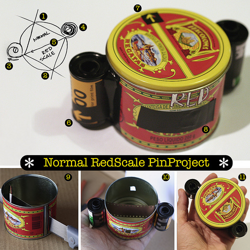
BiCam | PinManteiga

Image by Damiao Santana
Acabei de montar o Standard/RedScale PinProject, vulgo &quotNaManteiga&quot e ainda não obtive os resultados. A idéia que produzir fotos Normais, RedScale e até mesmo Dupla Exposição (simultânea ou não) com a combinação dos dois modos. Deus queira que funcione.

1 – Buraco do lado Regular. Atenção, devemos adaptar o alumínio de cerveja no quadradinho aberto na lata. O aço da lata é duro demais e não recomendo ninguém fazer o pinhole na própria lata. Faça por sua conta e risco, se quiser. Cuidado com explosões.

two – Buraco do lado RedScale. O chamado processo RedScale ocorre ao expormos o filme á partir da face contrária. Em função de problema de filtragem dos espectros da luz temos um efeito avermelhado como resultado dessas fotografias.

three – Filme vazio. Ali no six temos a seta que indica o sentido de avanço da película.

four – Filme cheio. Na cabeça do eixo central desse filme devemos fazer a marcação que servirá de guia para o avanço de cada frame. Uma volta completa é suficiente para termos a estenopéica pronta para o próximo disparo.

five – Neighborhood onde percorre o filme em direção ao &quotfilme vazio&quot

7 – Seta de indicação do lado Standard. Serve também para mirarmos o alvo.

eight – Obturador/lente do lado RedScale.

9 – Fase inicial do processo de fabricação. Todo cuidado é pouco para não se cortar, tanto na faca quanto no aço da lata. Após o corte devemos virar as bordas para neutralizar locais cortantes.

10 – Fase intermediária, após instalação do filme. Nesse momento devemos marcar a filme vazio, para evitar se confundir mais adiante. Ah, devemos pintar o interiror da lata com tinta preta fosco ou cobrir tudo com fita isolante.

11 – Vista superior da pinHole.

=====
Filme: 135mm
Distância focal: 35mm
Fotograma: 36x65mm [sprockethole]

———-
I just mount the Standard / RedScale PinProject , vulgar &quotNaManteiga&quot and not but received the results. The concept to generate Normais photos, and even RedScale Double Exposure (simultaneous or not) with the mixture of the two modes. God wants to work.

1 – Hole on the Standard. Consideration need to adapt the aluminum beer cans in the boxes open. The steel of the can is too challenging and do not suggest any person do the pinhole in the tin. Do at your personal threat, if you want. Beware of explosions.

2 – Hole RedScale side. The method known as RedScale occurs when exposing the film from the opposite side. Based on the problem of filtering the spectra of light have an impact as a outcome of these reddish pictures.

3 – Film empty. Here we have six in the arrow indicating the direction of advancement of the film.

four – Complete Movie. As head of the central axis of the film should do the marking will serve as a guide for the advancement of every single frame. A complete turn is enough to have the estenopéica prepared for the subsequent shot.

five – Location the film runs toward the &quotempty film&quot

7 – Arrow to indicate the normal side. It also serves to mirarmos the target.

eight – Shutter / Lens RedScale side.

9 – Early stage of the manufacturing procedure. All care is just not to cut in each the knife as the steel of tin. Following cutting the edges ought to turn to neutralize neighborhood cutting.

10 – intermediate stage, following installation of the film. At this time we should make a film empty, is to steer clear of confusion later. Ah, the interiror ought to paint the can with matte black paint or cover it with tape.

11 – Top view of pinHole.

……………………..
Hyperlinks de uns cabas bons de pinhole:
Miguel Chikaoka
Dirceu Maués
Marcos Campos
Angeloni

Image from page 1003 of “Electric railway journal” (1908)

Verify out these electrical discharge wire cutting pictures:

Image from page 1003 of “Electric railway journal” (1908)

Image by Net Archive Book Pictures
Identifier: electricrailway511918newy
Title: Electric railway journal
Year: 1908 (1900s)
Authors:
Subjects: Electric railroads
Publisher: [New York] McGraw Hill Pub. Co
Contributing Library: Smithsonian Libraries
Digitizing Sponsor: Smithsonian Libraries

View Book Web page: Book Viewer
About This Book: Catalog Entry
View All Pictures: All Photos From Book

Click here to view book online to see this illustration in context in a browseable on the web version of this book.

Text Appearing Prior to Image:
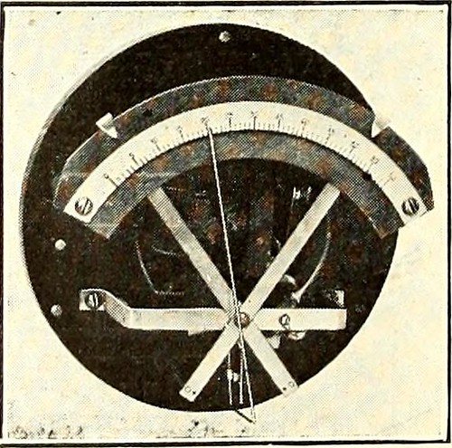
guide inmaking adjustments. The action of the governor is dependent on the Bourdon tube which isconnected to an independ-ent discharge pipe fromthe stress tank. Thefree end of the tube isconnected mechanically tothe indicator needle re-ferred to above. Afterthe governor has been setto the pressure range de-sired, it will automaticallymaintain the stress Pressure GOVERNOR within thoge ,j jt QnWITH CASE REMOVED . * gas or liquid program, thatwill not corrode the Bourdon tube. It can be utilised onboth a.c. and d.c. circuits, and will operate inside set-tings of from 3 to 12 lb. The device is created by the General Electric business,in sizes for rated pressures of 60, one hundred, 160, 300 and500 lb. Governors for higher pressures can also besupplied if desired. Adjustments of the cutting-in andcutting-out pressures are made by moving the pointersshown at the prime of the graduated scale. The case istapped and drilled at the bottom for the pressure pipeand for generating the electrical conduit connections.

Text Appearing After Image:
May 18, 1918 Electric Railway Journal * 975 Trolley Ear Length Is a Factor inWire-Put on Tests Recently Created Show That the Life of theWire Increases Proportionately With theLength of the Ear By G. H. Bolus Designing Engineer, Ohio Brass Organization, Mansfield, Ohio Companies of overhead line material listtrolley ears in all lengths from 7 in. to 15 in.Sales records show that the railway companies of theUnited States and Canada are purchasing a lot more 15-in.ears than those of any other length. The averagerailway man doubtless has standardized on the lengthof ear which he has discovered from knowledge works wellon his line, but it is doubtful whether or not he directly asso-ciates the length of the trolley ear with the put on onthe trolley wire. Some railway properties make a practice of startingtheir installation with a 9-in. ear, operating it untilworn out and replacing with a 12-in. ear to cover upthe worn spots in the wire. The next renewal wouldbe with a 15-in. ear and later renewals would eitherbe m

Note About Photos
Please note that these photos are extracted from scanned page images that could have been digitally enhanced for readability – coloration and appearance of these illustrations may not perfectly resemble the original operate.

Image from web page 372 of “Radiography and radio-therapeutics” (1919)

Image by World wide web Archive Book Pictures
Identifier: radiographyradio001knox
Title: Radiography and radio-therapeutics
Year: 1919 (1910s)
Authors: Knox, Robert, 1868-1928
Subjects: Radiography Radiography Radiotherapy
Publisher: New York : Macmillan
Contributing Library: Francis A. Countway Library of Medicine
Digitizing Sponsor: Open Understanding Commons and Harvard Medical School

View Book Web page: Book Viewer
About This Book: Catalog Entry
View All Photos: All Photos From Book

Click right here to view book on the web to see this illustration in context in a browseable on-line version of this book.

Text Appearing Ahead of Image:
is not possible to recordupon a plate. But radiographs which are taken instantaneously are ofgreat value as confirmatory proof of changes in the organs, and shouldalways be taken to full the examination. The importance of havinga thoroughly trustworthy fluorescentscreen have to be borne in mind.It is also essential that the screenbe smooth on the surface, andkept scrupulously clean. Thelead glass protection ought to alsobe kept well polished, for even atrace of dirt or pencil mark on itssurface may lead to difficulty, theimportance of this point beingreadily understood where finedetail is getting dealt with. It is also of importance tohave the patient completely nonetheless,especially when radiography isemployed, because the slightestmovement throughout the exposuremay ruin the worth of a plate. The screening stand need to be connectedto earth by a wire, in order to steer clear of providing the patient a shock fromthe electrical discharges which are given off from the tube and metal fittingswhen the former gets challenging.

Text Appearing Right after Image:
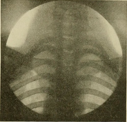
Fig. 247.—Normal reduce cervical and upper dorsalvertebrae. The apical element of both lungs isalso effectively shown. Radiography In radiography of the lungs for diagnostic purposes it is required touse a soft tube in order to obtain the best final results. It is detail in lungs andnot in bone that we appear for. A soft tube of about 3-4 inch spark-gap willallow a massive quantity of current to pass by means of it, and will give extremely gooddetail in the soft parts. Time exposures of any length are of no great worth for diagnosis ifwe are to get plates which will to any extent reproduce what we have seenon the screen, the exposure need to be exceedingly quick in truth, the shortestobtainable is the very best. With a potent modern installation the exposure 284 RADIOGRAPHY could be cut down to T£o of a second. The resulting image is of wonderful worth,because every thing is completely sharp, the heart being represented inoutline by the sharpest possible line. The diaphragm is also sharp, andmay be caught in a stage of

Note About Photos
Please note that these pictures are extracted from scanned web page photos that might have been digitally enhanced for readability – coloration and appearance of these illustrations might not completely resemble the original perform.

Image from page 594 of “The Gardeners’ chronicle : a weekly illustrated journal of horticulture and allied subjects” (1874)

Image from page 594 of “The Gardeners’ chronicle : a weekly illustrated journal of horticulture and allied subjects” (1874)

A few nice id od China grinding images I found:

Image from page 594 of “The Gardeners’ chronicle : a weekly illustrated journal of horticulture and allied subjects” (1874)

Image by Internet Archive Book Images
Identifier: gardenerschronic310lond
Title: The Gardeners’ chronicle : a weekly illustrated journal of horticulture and allied subjects
Year: 1874 (1870s)
Authors:
Subjects: Ornamental horticulture Horticulture Plants, Ornamental Gardening
Publisher: London : [Gardeners Chronicle]

View Book Page: Book Viewer
About This Book: Catalog Entry
View All Images: All Images From Book

Click here to view book online to see this illustration in context in a browseable online version of this book.

Text Appearing Before Image:
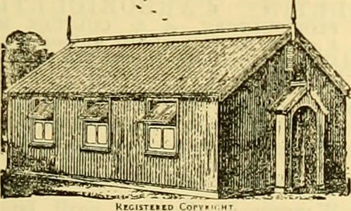
dry and soft onwet ground. Boxes, titf. and Is., from the Trade.Wholesale from PRICES PATENT CANDLE COMPANY(Limited). London. BROWN and BLACK F1BROUSPEAT, 25*.per Ton, or £5 per Truck of 4 tons; Bags, 5s. each;10 Bags. 45*. PEAT, for forming Rhododendron, Bog, and American PlantBeds, 2s. per Too, or £4 4s. per Truck of 4 tons; Bags bs.each ; 10 Bags, 45s. THOMAS WALKER. Tekels Park, Camberley. Surrey. SPECIAL RIVETED TRENTHAM BOILERS. Wrought, Welded, SADDLE, TUBULAR, INDEPENDENT,and ALL OTHER kimlsof BOILERS. HOT-WATER HEATING APPARATUS, with PIPES, VALVES, and FITTINOS, erected complete,and guaranteed. FRED SILVESTER & CO.,CASTLE HILL WORKS. NEWCASTLE. STAFFORDSHIRE. MERRYWEATHERS NON-KINKABLE RED-GREY GARDEN HOSE. Sole Manufacturers, MERRYWEATHER and SONS. 63, Long Acre, London. Stewards, Bailiffs, and Head Gardeners should apply for our pamphlet. Water Supply to Mansions. BOULTON & PAUL, Manufacturers, NORWICH.PORTABLE IRON and WOODEN BUILDINGS, For Leasehold Property.

Text Appearing After Image:
Hospital, School, or Mission Room. Illustrated Catalogue, containing over luO denigi.s, free onapplication. U IX CABINET PORTRAITS, 3s.; three for O 2s. Twelve Carte Portraits, 2s. id. ; six for Is. 4<f.Eight-inch Enlargement, 3s.; three for 6s. Stamp size. 24 forIs. <od.; 100 for 3s. 3d. Send Carte or Cabinet and Postal Order,and in about ten davs you will receive Highly-finished Copies,with Original.—FRANCIS AND CO.. 29, Ludgatehill, London. REVUE de lHORTICULTURE BELGEet ETRANGtlRE (Belgian and Foreign HorticulturalReview)—14th year.—Among the principal Contributors are :—A. Allard, E. Andre, C. Baltet, F. Burvenich, F. Crepin,O. de Kerchove de Denterghem, P. E. de Puydt, A. M. C.Jongkindt Couinck, J. Kicki.T. Moore, C. Naudin, B. Oliveira,H. Ortgies, E. Pynaert, E. Rodigas, O. Thomas, A. van GeertSon. H. J. van Hulle, J. van Volxem, H. J. Veitch, A. Wertmael. and P. Wolkenstein. This illustrated Journal appears on the 1st of every month,in parts of 24 pages, 8vo, wit

Note About Images
Please note that these images are extracted from scanned page images that may have been digitally enhanced for readability – coloration and appearance of these illustrations may not perfectly resemble the original work.

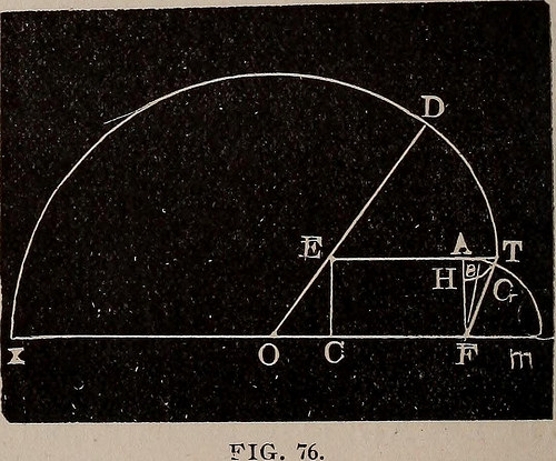
Image from page 209 of “A complete and practical solution book for the common school teacher” (1899)

Image by Internet Archive Book Images
Identifier: completepractica00fair
Title: A complete and practical solution book for the common school teacher
Year: 1899 (1890s)
Authors: Fairchild, J[ohn] T[heodore] [from old catalog]
Subjects: Arithmetic Geometry
Publisher: Crawfis College, Ohio, The author

View Book Page: Book Viewer
About This Book: Catalog Entry
View All Images: All Images From Book

Click here to view book online to see this illustration in context in a browseable online version of this book.

Text Appearing Before Image:
24.63ft.2+2)=DL=17.41 FIG. The area included inDKGL has been grazedtwice, hence its area mustbe taken from the areaalready found. (6) DP=DS=20 ft. (7) HG = OD=40V2,or56.56. (8) AH=|OD = HD=28.28ft (9) AG=CG=60 ft.(10) (ID (12) V(24.632+2)=DL = 17.41 ft., side of square KL, and its area is 17.412 =303.108 sq. ft. (13) The segments KSG and PLG are equal. (14) KS=LP=20 ft.—17.41_ft.=2.59ft. (15) Area of segments is (KS3-4-KGx4) +f of (KSx KGx2) =60.372 sq. ft. (16) Area grazed twice is 303.108+60.372=363.48 sq. ft. (17) .. The horse grazes over 23592+5654 88—363.48=28853.4 sq. ft. PROBLEM 391.A stake to which a horse is tethered, is 120 ft. from, the corner of abarn 60 ft. long-, 40 ft. wide, and in line with the long- side of the barn:if the rope is 120 ft. long-, over how much ground can the horse graze? Solution. Let FCEA repre-sent the barn. O represents thepoint at which thehorse is tethered. OC = 20ft.,CE=40ft. OE (1)(2) (3)(4) 202)

Text Appearing After Image:
v/(402= 44.721+ ft. (5) 44.721 : 20::sin90° : sin26° 34r = an g 1 eCEO. (6) The large angle FXDO=270°+26° 34=296H°- (7) 360° : 296H°::12027r : 37267.753 sq. ft., area of FODX. (8) (40×20)+2 = 400 sq. ft., area of triangle COE. MENSURA TION. 195 (9) Angle DET=90°—26° 34=63° 26. (10) DE=120 ft.—44.72 ft. =75.28 ft. (11) 360° : 63i|°::75.2827T : 3137.07 sq. ft., area of TED. (12) MF=120 ft.—(60 ft.+20 ft.)=40 ft. (13) tt(402-^4) =1256.64 sq. ft., area of MFA. (14) AT = 120 ft.—(60 ft.+44.75 ft.) =15.28 ft. (15) tt(15.282 ft.H-4) =182.374 sq. ft., area of ATH. (16) The area of AGH is common to the two sectors FMA and ATH, hence its area must be subtracted from thetwo. (17) Area of GAH = area of sector AGH + (area of sector FGA—area of triangle FGA). (18) In the triangle FGA, FA=40 rd., and AS = 7.64 rd. (19) 40 : 7.64::sin90° : sinll°. (20) Angle AFS = 11°. Angle FAS=90°—11°=79°. (21) 360° : 79°::15.282tt : 160.96 sq. ft., area of sector AGH. (22) 360° : 2

Note About Images
Please note that these images are extracted from scanned page images that may have been digitally enhanced for readability – coloration and appearance of these illustrations may not perfectly resemble the original work.