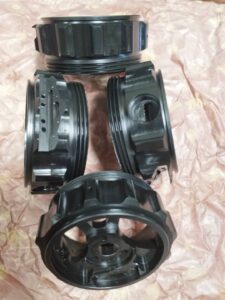
CNC Precision Machining Company Setting a Work

The workpiece arrangement technique builds up a work counterbalance or beginning area for the WCS. AIll workpiece arranges for programming will be referred to from this beginning. This is set up by finding the work counterbalance or “move” from the MCS starting point to the proposed WCS birthplace.

Review that the MCS never changes position. It is referred to at a similar position each time the machine is homed. Consider this point a perpetual reference point. Since the situation of this machine starting point never shows signs of change, yet the work cause changes with each new workpiece arrangement, the work balance for the part is characterized as a distance referred to from the MCS root. A few controls consider this counterbalance a workshift in light of the fact that it basically moves the machine inception to the area of the work beginning (or the other way around relying upon the machine). Carbon fiber cnc service factory shows an illustration portraying work counterbalance.

On turning machines, the workpiece will change long and position from one occupation to another and requires the cause to be reset in the Z-pivot for each new position. Notwithstanding, the middle line of the workpiece and the middle line of the axle hub are constantly adjusted, so the cause for the X-pivot stays as before from one occupation to another.

There are numerous varieties in the manner every maker’s machine is set up. The standards in the models portrayed next ought to apply to all machine controls.

Fundamental strides for setting a work balance:

  • The workpiece is introduced in the machine.
  • The turret is ordered to a confronting apparatus by utilizing the device change order.
  • The Z-hub is run to bring the confronting instrument close to the furthest limit of the workpiece.
  • The axle is begun utilizing the legitimate M3 or M4 code in MDI mode.
  • The part is looked by running a confronting device across the work utilizing the handwheel until the face is tidied up (no surface left un-machined).
  • The turret is run to a protected position and filed to a vacant position.
  • A gage block is held against the essence of the part.
  • The face of the turret is gradually and painstakingly ran against the gage block until a slight drag is felt. The length of the square is the separation from the planned part beginning to the essence of the turret (the reference point).
  • This gage block length is deducted from the current MCS Z-pivot position.
  • The coming about esteem addresses the separation from the MCS beginning to the WCS source for the Z-hub and is gone into the work balance page in the MCU.

The china cnc machining process supplier shows an illustration portraying the part, gage square, and turret being utilized to set a work balance.

It is a common misinterpretation that the drawtube string commitment affects cinching pressure. The drawtube just sets the size range among open and shut position. Eventually, the grasping pressing factor is resolved exclusively by the machine’s air or pressure driven controller for the collet/hurl nearer framework.

Some turning MCUs such as precision stainless steel cnc turned parts manufacturers utilize a less complex technique, and as opposed to deciding a genuine distance, they simply require a “set Z” catch to be squeezed. The MCU consequently plays out the computation and stores the right an incentive on the work counterbalance page.
Canned Cycle Machining Process

Drilling. reaming, counter boring, and sub-setting tasks can be modified utilizing drilling canned cycles. The G74 drill cycle is frequently utilized on Fanuc turning machines and allows a peck augmentation to interrupt chip stream, forestalling long, tacky chips. The arrangement generally requires two G74 blocks. The peck augmentation is indicated with a Q-esteem. A Q-estimation of 0.25 would make the instrument withdraw once for each 0.25 of in-feed.

A few machines don’t permit a decimal in the Q-esteem and follow a 4-place design. For this situation the 0.25 would be entered as Q2500. A R-esteem determines the sum the device will withdraw after each peck. The all out supreme Z-profundity is customized as a negative an incentive in the G74 block. The customized Z-profundity should represent the length of the drill tip. Programming to accomplish a 5/16″ measurement opening that is 1.125″ profound.

On the off chance that commotion in a solitary pass without any pecks, a canned cycle is regularly not utilized, yet it is conceivable to utilize the G74 cycle if the Q-esteem is set equivalent to the full Z-profundity. With all drill cycles, the drill ought to be positioned toward the beginning area of the opening with freedom in the Z-direction when the cycle is imitated The drill will automatically re-visitation of that position toward the finish of the cycle china 4 axis cnc machining service suppliers shows a Fanuc program for performing a G74 holemaking cycle with pecks.

Boring Canned Cycles for Haas

Haas offers three different drilling canned cycles for turning machines: a G81 for a solitary pass (no peck), a G82 for single pass with a stay, and a G83 for peck drilling with a full withdraw. The complete total Z-profundity is customized as a negative an incentive for all cycle. At the point when an instrument should cut cleanly at the lower part of an opening, the G82 cycle is utilized. This cycle delays the device toward the end Z position when a P.value (number of milliseconds is indicated.

When utilizing a G83, the peck addition is determined with a Q-esteem. A Q-estimation of 0.25″ would make the apparatus completely withdraw once for each 0.25* of in-feed. A R-esteem determines the position the device will re-visitation of toward the finish of the cycle. Pecision cnc machining service factory shows a Haas program playing out a drilling cycle with a solitary pass (no pecks).

cnc precision machining company shows a Haas program playing out a drilling cycle with pecks. The table beneath shows the organizations for each drilling cycle referenced.

Tapping Canned Cycles

Understand that a tap is stiffening During tapping, the machine tomahawks just position the tap and follow along as the tap is pulled in to the work. As a tap starts cutting, the shaft turn and the feed should be accurately synchronized with the goal that the tap doesn’t tie and break under strain. A CNC machine has no sensitivity and can’t feel resistance or front when tapping. As the tap moves toward its end position, the machine should decelerate axle speed and feed proportionately with the goal that both stop promptly when the tap arrives at the last profundity. Fill the tap should converse to withdraw from the opening. Since the tap is fully occupied with the work, the shaft speed and feed should proportionately quicken to withdraw the tap from the opening without breaking.

A tap propels into the work one string for every unrest (for single lead strings). Accordingly, the feed rate per insurgency is equivalent to the essence of the tap.

This article is from http://www.tinymachining.com

Tap Uses

Prior to tapping a gap, be certain the opening was bored with the right tap drill size and that it is away from chips and trash. For china precision machining parts suppliers, it is a smart thought to subset the opening to be tapped to the significant measurement of the string before beginning the tapping activity. This has a few advantages, for example, assisting with forestalling a burr at the head of the tapped opening and helping in beginning the tap (and the latch that will be strung into the gap).

When the gap has been readied, the V workpiece ought to be safely mounted in a tight clamp with the gap situated vertically. Taps might be driven with either a T-handle tap wrench or a straight tap wrench. T-handle torques are regularly utilized for littler tap measures and manage the cost of better feel and affectability for how much force is being applied to help abstain from breaking the tap.

Straight tap handles typically give more influence, which encourages you to apply the higher force required for bigger tap sizes.

Check to be certain the front lines of the tap are sharp. Worn, dull taps may require over the top force to cut, bringing about tap breakage or strings fitting too firmly. Apply slicing liquid to the tap and begin transforming it into the opening while at the same time helping with descending weight. When the tap begins cutting, it will maneuver itself into the work. Invert somewhat every half to full go to stay away from chips stopping up the tap woodwinds and causing breakage. Take a gander at the tap from a few distinct points as you use it to guarantee the opening is being tapped straight. A blend or strong square can be utilized to check opposites. A square with opposite surfaces can likewise be utilized as a guide in cnc precision machining company.

In the event that the tap isn’t straight when you check, turn around it marginally and delicately fix as the tap is progressed.

In some cases chips will tie inside the flutes and cause breakage when the tap is chilled out. On the off chance that obstruction is felt when you back a tap off, turn it the forward way marginally and take a stab at chilling out once more. Littler tapped openings have all the more an inclination to obstruct, since their woodwinds are littler and have less zone to contain chips. At the point when you feel the tap contact the finish of a visually impaired gap, back it out furthermore, eliminate all trash still in the gap.

After the gap has been tapped and cleaned, check the fit and profundity with a mating part or a gage. In the event that the tapped opening is excessively close, almost certainly, the tap is dull and worn. China precision tooling manufacturers utilizing another tap generally takes care of this issue.

Baggy gaps can result if the gap is penetrated excessively enormous or if the tap isn’t kept straight during tapping. It is normal for an opening to be strung to a predetermined profundity, particularly strung visually impaired gaps. In these cases, it is helpful to decide the number of turns of the tap are expected to arrive at the necessary profundity. When utilizing inch-based taps, the quantity of turns required can be found by duplicating profundity by TPI.

Profundity of a string in an opening alludes to the usable measure of string. Recollect that a tap has a chamfer on the end, so those couple of tightened strings at the chamfer won’t produce full usable strings. These recipes are gauges in light of the fact that the quantity of deficient strings on a tap shifts as indicated by the sort of tap chamfer. Therefore, strings will regularly not be sufficiently profound. To check the profundity of the string in the wake of tapping, clean the chips/trash from the opening, at that point follow these means.

  • Measure the whole length of a screw that is the size of the strung opening, or the whole length of a strung fitting gage.
  • Thread the screw, or gage, into the tapped opening until it stops.
  • Use a caliper or profundity micrometer to quantify the uncovered length of the screw, or gage
  • Subtract that estimation from the whole length of the screw, or gage.
  • The result is the profundity of the strung segment of the gap.
  • If the strings are not profound enough, take away the real profundity from the necessary profundity.
  • For inch-based strings, increase that distinction by the TPI to decide the number of more turns of the tap are required.
  • For metric strings, separate that distinction by the pitch to decide the number of more turns of the tap are required.
  • Recheck to confirm right profundity. This article is from http://www.tinymachining.com/